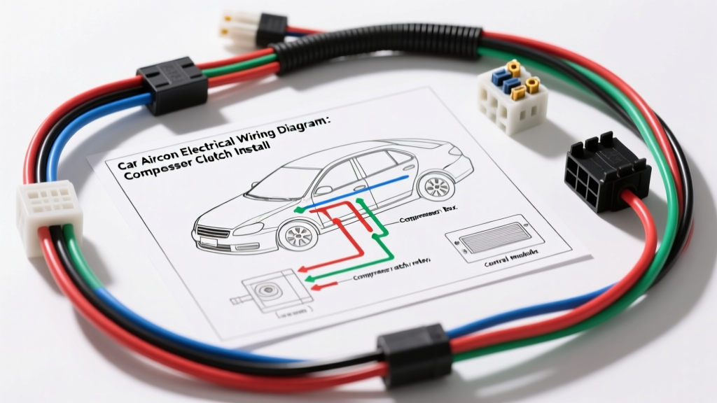
Decoding the Car Aircon Electrical Wiring Diagram for Custom Retrofits
When executing a custom engine swap, classic car restoration, or aftermarket A/C retrofit, relying on a comprehensive car aircon electrical wiring diagram is the difference between a reliable cooling system and a melted harness. Factory wiring harnesses are often degraded, incompatible with modern EFI systems, or entirely missing in project vehicles. Understanding the schematic allows you to build a robust, standalone compressor clutch circuit that integrates seamlessly with your vehicle's existing electrical architecture.
A properly designed A/C clutch circuit must handle significant inrush currents while protecting sensitive electronic control units (ECUs) from inductive voltage spikes. This practical installation guide breaks down the core components, wire gauge requirements, and step-by-step execution of a universal automotive air conditioning compressor clutch relay circuit. Whether you are installing a Vintage Air system or adapting a Sanden SD7 compressor, the electrical principles remain identical.
Anatomy of the A/C Clutch Control Circuit
Before cutting any wire, it is critical to understand the two distinct circuits depicted in any standard car aircon electrical wiring diagram: the Power Circuit and the Control Circuit.
- The Power Circuit: This handles the heavy current required to engage the electromagnetic clutch coil. It runs directly from the battery positive terminal, through a 30-amp inline fuse, to Pin 30 of a standard ISO mini relay. The output (Pin 87) feeds directly to the compressor clutch coil.
- The Control Circuit: This low-current loop dictates when the relay triggers. It typically originates from a switched 12V ignition source, passes through the cabin thermostat (evaporator switch), routes through the engine bay binary pressure switch, and finally terminates at the relay coil (Pins 85 and 86).
According to Littelfuse Automotive Relay Specifications, while a standard A/C clutch coil draws only 3 to 4.5 amps at a steady 12 volts, the initial inrush current can spike above 15 amps for several milliseconds. This necessitates the use of a 30-amp rated ISO relay rather than relying on the dash switch or thermostat to carry the load directly.
Wire Gauge, Color Codes, and Component Specifications
Adhering to SAE J1128 Low Tension Primary Cable Standards ensures your wiring can handle the thermal and mechanical stress of the engine bay. Below is the specification chart for a standard universal A/C clutch installation.
| Circuit Segment | Recommended AWG | Standard Color Code | Max Amp Load | Connector Type |
|---|---|---|---|---|
| Battery to Relay (Pin 30) | 10 AWG | Red | 30A | Ring Terminal (Heat Shrink) |
| Relay to Clutch (Pin 87) | 12 AWG | Dark Green | 15A | Delphi Weather-Pack 1-Way |
| Ignition to Thermostat (Pin 86) | 16 AWG | Pink or Red/White | 5A | Spade / Bullet Connector |
| Thermostat to Binary Switch | 16 AWG | Light Green | 5A | Binary Switch Plug (OEM style) |
| Binary Switch to Relay (Pin 85) | 16 AWG | Black | 5A | Ring Terminal / Relay Socket |
Step-by-Step Compressor Clutch Installation Guide
Step 1: Establishing the Power Feed and Inline Fusing
Begin by routing a 10 AWG red wire from the positive battery terminal to the engine bay firewall. Install a 30-amp maxi-fuse holder within 8 inches of the battery post to protect the entire length of the wire in the event of a short circuit. Terminate this wire into Pin 30 of your ISO relay socket. Ensure all ring terminals are crimped using a closed-barrel crimper and sealed with dual-wall adhesive heat shrink tubing to prevent corrosion.
Step 2: Routing the Clutch Feed and Grounding
Run a 12 AWG dark green wire from Pin 87 of the relay directly to the compressor clutch coil. The clutch coil itself is typically grounded internally through the metal casing of the compressor body. However, to ensure a flawless ground path, verify that the compressor is bolted to the engine block with clean, bare metal contact points. If the compressor is isolated by rubber vibration dampeners, you must run a dedicated 12 AWG black ground wire from the compressor casing to the engine block.
Step 3: Integrating the Binary Pressure Switch
The binary pressure switch is a critical safety device that prevents the compressor from engaging if refrigerant pressure is too low (which would destroy the compressor due to lack of oil circulation) or too high (which could burst a hose). Standard binary switches cut out at approximately 30 PSI on the low side and 400 PSI on the high side. Wire this switch in series on the control side of your circuit. If you are using a trinary switch (which also triggers the condenser fan at 250 PSI), ensure the third set of wires is routed to your fan relay trigger.
Step 4: Installing the Flyback Diode for EFI Protection
This step is frequently omitted in amateur car aircon electrical wiring diagram guides, leading to catastrophic ECU failures. An A/C clutch is a massive electromagnetic coil. When the relay cuts power, the collapsing magnetic field generates a high-voltage reverse polarity spike (flyback voltage) that can exceed 100 volts. In older carbureted vehicles, this spike simply causes a minor spark across the relay contacts. In modern EFI vehicles, this spike travels back through the control circuit and can fry the ECU's internal transistors. To prevent this, solder a 1N4007 rectifier diode across the relay coil pins (85 and 86), with the diode's cathode (striped end) facing the positive 12V source.
Terminal Crimping and Environmental Sealing Standards
The engine bay is a hostile environment characterized by extreme heat, oil mist, and high-pressure water. Standard vinyl-insulated crimp connectors will fail prematurely. For the connection at the compressor clutch, utilize a Delphi Weather-Pack or Metri-Pack sealed connector system. These connectors feature silicone rubber seals that compress around the wire insulation, providing a watertight barrier. Always use the correct ratcheting crimp tool designed for the specific terminal series to ensure the wire strands are compressed without being cut, maintaining maximum tensile strength and conductivity.
Diagnostic Troubleshooting: When the Clutch Won't Engage
Even with a perfect car aircon electrical wiring diagram, real-world variables can cause engagement failures. Use the following diagnostic decision tree to isolate the fault:
- Verify Refrigerant Charge: If the system is below 30 PSI, the binary switch will remain open. Connect a manifold gauge set to verify static pressure before testing electrical components.
- Check the Air Gap: The physical gap between the clutch friction plate and the compressor pulley must be between 0.020" and 0.030". If the gap is too wide due to wear, the electromagnetic field will be too weak to pull the plate in, especially when the engine is hot and system voltage drops. Use a feeler gauge and remove shims from the clutch hub to adjust.
- Perform a Voltage Drop Test: According to SAE standards, a healthy circuit should exhibit no more than a 0.5V drop across any connection or wire length under load. Set your multimeter to DC Volts. Place the red probe on the battery positive and the black probe on the clutch terminal while the system is commanded ON. If you read more than 11.0V at the clutch (assuming a 12.6V battery), you have excessive resistance in the power feed or the relay contacts are pitted.
- Test the Clutch Coil Resistance: Disconnect the clutch connector and measure resistance across the coil terminals using a multimeter. A healthy coil should read between 3.5 and 4.5 ohms. A reading of infinite resistance (OL) indicates an open internal winding, requiring a complete clutch coil replacement.
By strictly adhering to these wiring protocols and leveraging a detailed schematic, you ensure your vehicle's A/C system operates reliably under the harshest thermal and electrical loads. For deeper diagnostics and model-specific pinouts, always cross-reference your vehicle's factory service manual or Haynes Automotive Repair Manuals.