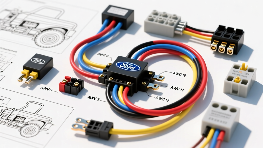
Introduction: The Economics of the Ford 9N 12-Volt Conversion
The Ford 9N, produced between 1939 and 1942, originally rolled off the assembly line with a 6-volt, positive-ground electrical system powered by a 3-brush generator. While historically accurate, this 6V architecture is notoriously inadequate for modern cranking demands, high-draw lighting, and electronic accessories. Upgrading to a 12-volt, negative-ground system utilizing a modern 1-wire alternator is the most common and effective restoration modification. However, executing this swap requires a precise understanding of the ford 9n wiring diagram 12 volt configuration, alongside a realistic budget and specialized heavy-duty tools. This guide provides a comprehensive cost and tool requirements analysis to ensure your conversion is both economically viable and electrically sound.
Essential Tool Requirements for the 12V Swap
Transitioning from a low-amperage 6V system to a high-capacity 12V system means dealing with significantly thicker battery cables and higher current loads. Standard automotive pliers and electrical tape will result in voltage drops, arcing, and potential electrical fires. According to the SAE J1128 Low Tension Primary Cable Standard, heavy-duty battery circuits require specific crimping pressures and insulation ratings. You must procure the following tools before beginning the harness teardown:
- Heavy-Duty Cable Crimper (1/0 to 4 AWG): Essential for terminating 1/0 AWG battery cables. Ratchet-style or hydraulic crimpers ensure a cold-weld connection that prevents moisture ingress and high-resistance hot spots.
- Wire Strippers (8 to 18 AWG): For precision stripping of primary ignition and alternator exciter wires without nicking the copper strands.
- Digital Multimeter (DMM): Required for verifying continuity, testing the 12V coil primary resistance (typically 1.2 to 1.8 ohms), and confirming negative ground polarity post-conversion.
- Soldering Torch & Rosin-Core Solder: While crimping is preferred for 1/0 AWG, soldering the heavy lugs provides a secondary mechanical bond and seals out agricultural moisture.
- Adhesive-Lined Heat Shrink Tubing: Mandatory for sealing 8 AWG and 1/0 AWG terminals. The inner adhesive melts to create a waterproof barrier against fertilizer and diesel fumes.
- Torque Wrench (Inch-Pounds): Coil and solenoid terminal nuts are easily stripped. Alternator and solenoid studs should be torqued to exactly 45-60 in-lbs to prevent loosening under tractor vibration.
Component Cost Breakdown: 6V vs. 12V Parts
One of the primary concerns for restorers is the financial impact of abandoning the original 6V generator and voltage regulator. Fortunately, the aftermarket support for Ford N-Series tractors makes this conversion highly cost-effective. Below is a realistic cost analysis for a complete, reliable 12-volt upgrade using premium aftermarket and OEM-equivalent components.
| Component | Specification / Part Type | Estimated Cost (USD) |
|---|---|---|
| Alternator | Delco 10SI 1-Wire (63A or 94A) | $65.00 - $85.00 |
| Ignition Coil | 12V Coil w/ Internal 1.5 Ohm Resistor | $25.00 - $35.00 |
| Starter Solenoid | 12V Ford-Style 4-Post Relay | $15.00 - $22.00 |
| Battery Cables | 1/0 AWG Welding Cable (Custom Cut) | $30.00 - $45.00 |
| Primary Wiring | 14 AWG & 10 AWG GXL Wire Loom | $20.00 - $25.00 |
| Headlights | 12V 50W Sealed Beam (H6024) | $35.00 - $50.00 |
| Terminals & Lugs | Heavy-Duty Copper Lugs & Heat Shrink | $15.00 |
| Total Estimated Cost | Complete 12V Electrical Overhaul | $205.00 - $277.00 |
Note: If you choose to retain a standard 12V coil without an internal resistor, you must add a $6.00 external 1.5-ohm ceramic ballast resistor to the ignition circuit to prevent the distributor points from burning out due to 14.4V alternator output.
Ford 9N 12 Volt Wiring Diagram & Circuit Routing
The core of the conversion relies on reversing the ground polarity and bypassing the obsolete 6V voltage regulator. The original 9N wiring harness should be entirely removed, as the cloth-braided 6V wires are often brittle and undersized for modern 12V accessory loads. For a detailed visual reference and community-tested schematics, the Yesterday's Tractors 12-Volt Conversion Guide remains the gold standard for N-Series restorers.
1. Grounding and Polarity Reversal
The original 9N was Positive Ground. The new 12V system MUST be Negative Ground. Connect the Negative (-) terminal of the 12V battery to the tractor frame or transmission housing using a 1/0 AWG ground strap. Ensure the mounting surface is ground down to bare, clean metal. Paint and rust act as insulators, causing severe voltage drops during starter engagement.
2. Alternator and Main Power Routing
The 1-wire Delco alternator simplifies the harness. Run an 8 AWG red wire from the alternator's BAT terminal directly to the battery-side (BAT) post of the starter solenoid. This setup bypasses the ammeter for the high-current charging circuit, preventing the ammeter from melting if the alternator outputs its full 63 amps. The alternator self-excites when the engine RPMs reach approximately 1,200 RPM, eliminating the need for an ignition-switched exciter wire.
3. Ignition Circuit and Ballast Resistor
Route a 14 AWG wire from the ignition switch output to the input side of the ballast resistor (if using a standard coil). From the output side of the resistor, run a 14 AWG wire to the positive (+) terminal of the ignition coil. The negative (-) terminal of the coil connects directly to the distributor points. Critical: Ensure the coil positive is connected to the side receiving switched power, and the negative goes to the points. Reversing this reduces spark intensity by up to 20%.
4. Ammeter Reconfiguration
The original 9N ammeter will read backwards (discharge) when the 12V alternator is charging because the current flow direction has reversed. To fix this, simply swap the two wires on the back of the ammeter gauge. Do not swap the heavy battery cables; only swap the smaller gauge wires feeding the instrument cluster.
Wire Gauge (AWG) & Color Code Reference Chart
Adhering to proper American Wire Gauge (AWG) sizing is non-negotiable. Undersized wires will overheat, especially in the high-ambient-temperature environment near the 9N's engine block and exhaust manifold.
| Circuit | Required AWG | Standard Color Code | Max Amperage Load |
|---|---|---|---|
| Battery (+) to Solenoid | 1/0 AWG | Red | 250A+ (Cranking Surge) |
| Solenoid to Starter Motor | 1/0 AWG | Black or Red | 250A+ (Cranking Surge) |
| Battery (-) to Chassis Ground | 1/0 AWG | Black | 250A+ (Cranking Surge) |
| Alternator BAT to Solenoid BAT | 8 AWG | Red | 65A - 100A |
| Solenoid to Ammeter / Dash Feed | 10 AWG | Red | 30A |
| Ignition Switch to Coil/Resistor | 14 AWG | Black or Purple | 5A - 8A |
| Coil to Distributor Points | 14 AWG | Black | 5A - 8A |
| Headlight Feed (per side) | 12 AWG | Yellow or Brown | 10A |
Common Failure Modes & Troubleshooting Decision Tree
Even with a perfect ford 9n wiring diagram 12 volt schematic, real-world agricultural environments introduce variables that cause electrical faults. Use this expert decision tree to diagnose post-conversion issues.
Symptom: Alternator is not charging the battery.
- Cause 1: 1-wire alternator has not received the 'exciter' RPM threshold. Fix: Rev the engine to 1,500 RPM once upon startup to initiate the internal voltage regulator.
- Cause 2: Poor ground at the alternator mounting bracket. Fix: The Delco 10SI grounds through its mounting ears. Remove the alternator, sand the paint off the tractor's mounting bracket, and reinstall with star washers.
- Cause 3: Blown internal diode trio due to disconnecting the battery while the engine was running. Fix: Replace the alternator; never pull a battery cable to 'test' a 12V alternator.
Symptom: Distributor points burn out or pit rapidly.
- Cause 1: Ballast resistor bypassed or omitted. Fix: Verify 14.4V is NOT reaching the points. The voltage at the coil negative terminal should drop to roughly 7V-9V when the points are closed. Install a 1.5-ohm ceramic ballast resistor immediately.
- Cause 2: Condenser failure. Fix: Replace the 6V condenser with a modern 12V-specific condenser (0.15 to 0.25 microfarads). A weak condenser causes excessive arcing across the points regardless of system voltage.
Symptom: Tractor cranks slowly despite a new 12V battery.
- Cause 1: Using the original 6V starter motor on a 12V system without upgrading the cables. Fix: The 6V starter will spin much faster on 12V, drawing massive amperage. Ensure your 1/0 AWG cables are less than 4 feet in total length and that all lugs are hydraulically crimped, not merely hammered flat.
- Cause 2: Starter solenoid voltage drop. Fix: Measure voltage at the solenoid BAT post during cranking. If it drops below 10.5V, the connection from the battery is compromised by corrosion or undersized wire.
By investing in the correct heavy-duty crimping tools, adhering strictly to the AWG specifications, and understanding the polarity reversal requirements, your Ford 9N 12-volt conversion will yield decades of reliable, high-torque starting and brilliant illumination.