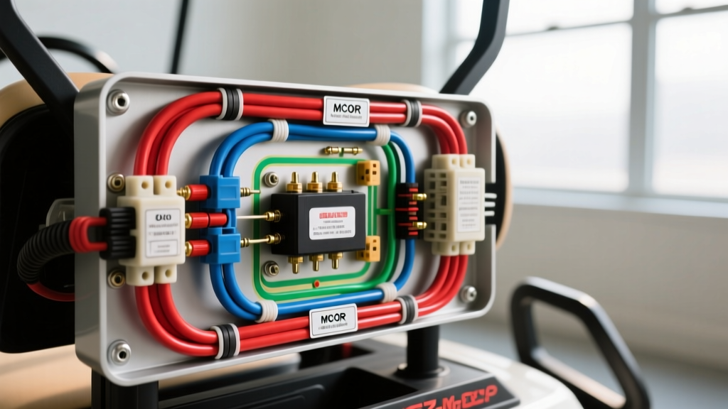
Introduction to 36V Series Drive Architecture
When analyzing a 36 volt golf cart wiring diagram, technicians must understand the fundamental difference between series-wound and shunt-wound (regen) DC motor systems. This advanced technical deep dive focuses on the classic 36V series-wound architecture, most notably utilized in the EZ-GO TXT platform. A 36V nominal system is achieved by wiring six 6V deep-cycle lead-acid batteries in series, yielding a fully charged resting voltage of approximately 38.2V to 38.4V. Understanding the precise routing of both the high-current traction circuit and the low-current control logic is critical for diagnosing voltage drops, solenoid failures, and micro-switch sequencing faults.
High-Current Traction Circuit Analysis
The high-current path is responsible for delivering up to 300+ amps of peak surge current from the battery bank to the series-wound DC motor. This circuit relies on heavy-gauge copper cabling to minimize resistance and prevent catastrophic voltage sag under heavy load or incline climbing.
Battery Pack to Solenoid Routing
The main positive output of the 36V battery bank originates at the positive terminal of Battery #1. A 2 AWG pure copper cable (Red insulation) routes this current to the primary large terminal of the main contactor (solenoid). The battery interconnects linking the six 6V batteries must utilize 6 AWG or 4 AWG stranded copper cables. According to NFPA 70 (NEC) Article 480 guidelines for storage batteries, all battery terminal connections must be torqued to manufacturer specifications—typically 110 to 120 in-lbs for 6 AWG links—to prevent high-resistance hot spots that cause terminal melting.
Motor Field and Armature Connections
Once the solenoid is energized, current flows from the secondary large terminal through another 2 AWG Red cable to the motor's Armature 1 (A1) terminal. In a series-wound motor, the current then passes through the armature windings and exits via Armature 2 (A2). From A2, a 2 AWG Black cable routes to the Forward and Reverse (F&R) switch. The F&R switch dictates the polarity of the current entering the stator field windings (S1 and S2), which in turn determines the rotational direction of the motor. Finally, the current returns to the main negative bus (Battery #6 negative) via a 2 AWG Black cable. All motor stud connections require a torque of 110 in-lbs to ensure optimal electrical contact surface area.
Solenoid Pre-Charge and Inductive Protection
A critical, often overlooked component in the 36 volt golf cart wiring diagram is the solenoid protection circuit. Across the two large terminals of the main solenoid, two components must be installed in parallel:
- Pre-Charge Resistor: Typically a 470-ohm, 2-watt ceramic resistor. Before the main solenoid contacts close, this resistor allows a small trickle current to flow into the motor controller and motor windings. This equalizes the voltage across the large contacts, preventing the high-amperage arc that would otherwise pit and weld the contacts shut upon closure.
- Freewheeling Diode: A heavy-duty flyback diode (rated for at least 600V and 5A) is installed across the small activation terminals of the solenoid. When the control circuit is broken and the magnetic field of the solenoid coil collapses, it generates a massive inductive voltage spike. The diode safely routes this kickback current back through the coil, protecting the upstream throttle micro-switches from arcing and premature failure.
Low-Current Control Circuit & Micro-Switch Sequencing
The control circuit operates at 36V but carries minimal current (under 2 amps). It utilizes 14 AWG to 16 AWG stranded primary wire, adhering to SAE J1128 standards for low-tension primary cable. This circuit's sole purpose is to energize the solenoid's activation coil, which requires a minimum of 32V to pull the heavy internal plunger against the spring pressure.
F&R Switch and Throttle Logic
The activation sequence begins at the key switch, which sends 36V down a 16 AWG Red wire to the F&R switch. The F&R switch contains an internal micro-switch that only closes when the lever is fully engaged in either Forward or Reverse. If the lever is in neutral, the circuit remains open. From the F&R switch, a 16 AWG Blue wire routes to the throttle box. In older V-Glide systems, this passes through a rheostat; in modern MCOR (Motor Controller Output Regulator) systems, it triggers an optical or Hall-effect sensor and a mechanical micro-switch. When the accelerator pedal is depressed past the initial take-up slack, the micro-switch closes, sending 36V via a 16 AWG Yellow wire to the small positive terminal of the solenoid. The small negative terminal of the solenoid is grounded directly to the main negative bus via a 16 AWG Black wire, completing the activation circuit.
36 Volt Golf Cart Wiring Diagram Specification Table
| Circuit Segment | Wire Color | AWG Size | Origin | Destination | Primary Function |
|---|---|---|---|---|---|
| Main Traction Positive | Red | 2 AWG | Battery 1 (+) | Solenoid Large Terminal | Delivers primary pack voltage to contactor |
| Motor Armature Feed | Red | 2 AWG | Solenoid Large Terminal | Motor A1 Terminal | Routes switched high-current to armature |
| F&R Directional Link | Black | 2 AWG | Motor A2 Terminal | F&R Switch Bottom Post | Completes armature circuit and allows polarity reversal |
| Activation Feed | Blue | 16 AWG | F&R Switch Micro | Throttle Micro-Switch | Carries 36V logic signal pending pedal depression |
| Solenoid Coil Positive | Yellow | 16 AWG | Throttle Micro-Switch | Solenoid Small Terminal (+) | Energizes contactor coil to close main contacts |
| Solenoid Coil Ground | Black | 16 AWG | Solenoid Small Terminal (-) | Main Negative Bus | Provides return path for activation coil current |
Advanced Troubleshooting: Voltage Drop & Solenoid Chatter
When diagnosing a 36V system that fails to engage, technicians must avoid the common pitfall of simply replacing the solenoid. Instead, perform a systematic voltage drop test using a digital multimeter (DMM) capable of reading DC millivolts.
Diagnosing Solenoid Chatter
If the solenoid emits a rapid clicking or 'chattering' sound when the pedal is pressed, the activation coil is receiving insufficient voltage to maintain the magnetic hold.
- Set your DMM to DC Volts.
- Place the black probe on the main negative battery terminal and the red probe on the small positive terminal of the solenoid.
- Depress the throttle. You should read within 0.5V of the total pack voltage (e.g., 37.8V on a 38.2V pack).
- If the reading drops below 32V, the issue is upstream. Move the red probe backward through the circuit: first to the throttle micro-switch input, then to the F&R switch output, and finally to the key switch output.
- A voltage drop greater than 0.2V across any single switch or connector indicates oxidized contacts, loose crimps, or internal switch failure.
Welded Solenoid Contacts (Runaway Cart)
If the golf cart moves forward or reverse without the key being on, or immediately upon turning the key before the pedal is pressed, the main high-current contacts inside the solenoid have welded together. This is almost always caused by a missing or failed pre-charge resistor, or pulling the cart under heavy load without allowing the solenoid to fully seat. To verify, disconnect the main positive battery cable and test for continuity across the two large solenoid terminals with the DMM set to Ohms. Any reading below infinite (OL) confirms welded contacts. The solenoid must be replaced, and the pre-charge resistor circuit must be verified and repaired before re-energizing the system.
Authoritative References
- SAE International - J1128: Low Tension Primary Cable (Standards for 16 AWG control circuit insulation and temperature ratings).
- NFPA 70: National Electrical Code (NEC) Article 480 (Storage battery installation, interconnect gauge, and torque requirements).
- Curtis Instruments - DC Motor Controller Technical Manuals (Reference for series-wound motor commutation and solenoid pre-charge logic).