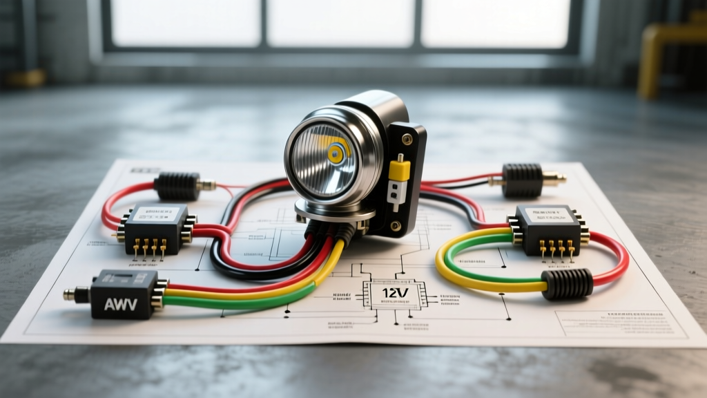
Project Scope: Solid-State Photo Sensor Headlight Upgrade
Integrating automatic headlights into a classic muscle car, early 4x4, or restomod project dramatically improves daily drivability and safety. While modern vehicles use complex Body Control Modules (BCMs) and LIN-bus networks to manage exterior lighting, a restomod requires a standalone, robust, and highly reliable analog solution. This guide details the complete photo sensor wiring diagram and harness fabrication required to upgrade a classic vehicle with an automatic twilight sentinel system using a 12V solid-state photo control module and high-current Bosch-style relays.
Unlike older vacuum-based or bi-metallic strip twilight switches found in 1970s luxury cars, modern solid-state photo sensors utilize a Light Dependent Resistor (LDR) or photodiode paired with an internal operational amplifier (op-amp) and hysteresis circuit. This ensures precise lux-threshold triggering without the mechanical bounce or delayed thermal reaction times of vintage components. By mapping out the correct photo sensor wiring diagram and pairing it with a properly fused relay harness, you can safely drive high-amperage halogen or LED headlight arrays without overloading the factory dashboard headlight switch.
Analyzing the Photo Sensor Wiring Diagram
The core of this upgrade relies on a standard 4-pin 12V photo control module. These modules are designed to handle inductive loads up to 10 amps directly, but for automotive headlight circuits—which frequently draw 15 to 25 amps combined and possess high inrush currents—we use the sensor strictly as a low-current logic switch to trigger the relay coils. The sensor module features an internal N-channel MOSFET that switches the load wire to ground when ambient light drops below the preset threshold (typically 15-20 lux).
Understanding the photo sensor wiring diagram is critical to preventing parasitic draws and ensuring the system shuts off when the ignition is removed. The inclusion of an ignition-sense wire is a mandatory safety feature; without it, the headlights will remain illuminated if the vehicle is parked in a dark garage or if the sensor is covered by debris.
Module Pinout and Wire Color Code Matrix
The following table outlines the standard 12V photo sensor wiring diagram pinout, utilizing SAE J1128 cross-linked polyethylene (TXL) wire for optimal underhood heat resistance.
| Pin / Cavity | Wire Color | AWG Size | Function | Connection Point |
|---|---|---|---|---|
| 1 (Red) | Red | 16 AWG | +12V Constant Power | Battery Positive via 5A ATO Fuse |
| 2 (Black) | Black | 16 AWG | Chassis Ground | Clean Firewall Stud / Engine Block |
| 3 (White) | White | 18 AWG | Load (Ground Switch) | Relay Pins 85 (Low Beam & Parking) |
| 4 (Yellow) | Yellow | 18 AWG | Ignition Override | Fuse Box IGN 12V (Switched) |
Relay Harness Fabrication & Sizing
Because the photo sensor module is only rated for low-current logic switching in this configuration, we must build a relay harness to carry the actual headlight current. We will use two standard ISO mini (Bosch-style) 5-pin relays: one dedicated to the parking/marker lights, and one dedicated to the low-beam headlights. High beams are intentionally excluded from the automatic photo sensor circuit for safety and legal compliance reasons; they remain under manual control via the steering column dimmer switch.
According to AutoShop 101 Automotive Relay Circuits, when wiring multiple relay coils to a single solid-state ground switch, you must account for the cumulative coil current. A standard 12V automotive relay coil draws approximately 150mA. Two relays will draw 300mA, well within the 10A rating of the photo sensor's internal MOSFET. However, you must install flyback diodes across the relay coils to protect the sensor.
Power Distribution and Relay Specifications
| Circuit | Relay Pins | Wire AWG (TXL) | Fuse Rating | Max Continuous Load |
|---|---|---|---|---|
| Parking / Marker Lights | 30 (In) / 87 (Out) | 14 AWG | 10A | 8A |
| Low Beam Headlights | 30 (In) / 87 (Out) | 12 AWG | 20A | 16A |
| Relay Coil Power Feed | 86 (In) | 14 AWG | 5A | 1A |
Step-by-Step Wiring Execution
Executing this photo sensor wiring diagram requires meticulous attention to environmental sealing and voltage drop mitigation. Follow these steps to ensure a factory-grade restomod installation.
- Sensor Placement and Routing: Mount the photo sensor module on the top of the dashboard, facing forward through the windshield, or in the front grille area if the module is potted and IP67 rated. Avoid placing it near underhood LED light bars or exhaust heat sources. Route the harness through the firewall using an existing rubber grommet to prevent chafing.
- Install Flyback Diodes: Solder a 1N4001 rectifier diode across the coil terminals (Pin 85 and Pin 86) of each relay. The silver cathode stripe must face Pin 86 (12V+), and the anode must face Pin 85 (the sensor load wire). This clamps the inductive voltage spike generated when the relay coil de-energizes, preventing the destruction of the photo sensor's internal switching transistor.
- Wire the Ignition Override: Connect the Yellow (Pin 4) wire to a true ignition-switched 12V source. This ensures that if you turn off the engine and remove the key, the photo sensor module enters a sleep state and cuts power to the relays, preventing a dead battery even if the car is parked in a pitch-black environment.
- Terminate with Weather-Pack Connectors: Do not use standard butt connectors under the hood. Utilize Delphi Weather-Pack 150 series terminals with silicone sealing plugs. This prevents capillary action, where moisture wicks up inside the wire insulation and corrodes the relay spades over time.
- Integrate with Factory Switch: To retain manual override capability, wire the factory headlight switch output to the relay Pin 87a (Normally Closed) or use a parallel diode-OR logic gate so that turning the manual switch on will bypass the photo sensor and energize the headlights regardless of ambient light.
Diagnostic Decision Tree: Sensor & Relay Faults
When troubleshooting a custom photo sensor wiring diagram, symptoms often point directly to specific installation errors. Use this matrix to diagnose common restomod lighting faults.
- Symptom: Headlights flicker rapidly at dusk or under tree canopies.
Cause: Lack of circuit hysteresis or sensor saturation.
Fix: Ensure the sensor is not reflecting off the interior dashboard. If using a raw LDR circuit, add a 100µF electrolytic capacitor across the sensor signal line to introduce a time-delay, or upgrade to a module with an integrated 10-second delay timer. - Symptom: Headlights remain on after the vehicle is turned off and parked outside.
Cause: Ignition override wire (Yellow) is connected to a constant 12V source instead of a switched IGN source.
Fix: Use a multimeter to verify the Yellow wire loses 12V when the key is in the OFF position. Re-tap to a proper ignition circuit. - Symptom: Photo sensor module becomes extremely hot or fails after a few weeks.
Cause: Missing flyback diodes on the relay coils, causing inductive kickback to punch through the module's internal MOSFET.
Fix: Replace the module and install 1N4001 diodes across Pins 85 and 86 on all triggered relays. - Symptom: Headlights dim slightly when the engine is idling.
Cause: Undersized power feed wire or poor chassis ground causing voltage drop.
Fix: Verify the main power feed from the battery is at least 10 AWG for the combined distribution block, and ensure all grounds are secured to bare, unpainted metal using star washers.
Reference Standards and Best Practices
When executing any vehicle wiring diagram modification, adherence to automotive standards ensures longevity and fire safety. All primary wire used in this photo sensor upgrade must meet the SAE J1128 Low Tension Primary Cable Standard. This specification mandates cross-linked insulation (such as TXL or GXL) capable of withstanding continuous underhood temperatures up to 125°C (257°F), which is critical when routing wires near exhaust manifolds or radiator cooling fans.
Furthermore, always utilize adhesive-lined marine-grade heat shrink (minimum 3:1 shrink ratio) over all soldered connections and diode integrations. This creates a waterproof, vibration-resistant seal that prevents the harsh underhood environment from degrading your custom automatic headlight harness. By combining the precise logic of a modern photo sensor with heavy-duty relay switching, your restomod gains modern convenience without sacrificing electrical reliability.