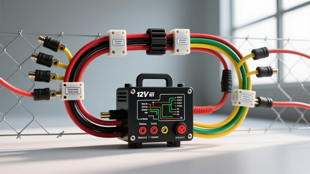
Introduction to Mobile UTV Electric Fence Systems
For modern ranchers and rotational grazing operations, mobile electric fencing powered by side-by-side vehicles has revolutionized pasture management. Utilizing a UTV like the Polaris Ranger 1000 or John Deere Gator to transport and power a 12V mobile energizer (such as the Gallagher M1200 or Parmak DF-SP-LI) allows for rapid deployment of temporary paddocks. However, integrating high-voltage pulse generators into the sensitive electrical architecture of modern off-road vehicles requires a meticulous approach. This advanced electric fence wiring diagram and technical guide provides the exact specifications, relay isolation logic, and SAE-standard wire routing required to protect your vehicle's ECU while delivering maximum joule output to the fence line.
The Danger of HV Transients on Automotive CAN Bus Networks
Modern UTVs are no longer simple mechanical machines; they rely on complex Controller Area Network (CAN bus) systems, electronic fuel injection (EFI) ECUs, and sensitive stator rectifiers. A 12V fence energizer generates a high-voltage pulse (often exceeding 8,000 volts) at roughly 1-hertz intervals. If wired directly to the vehicle's 12V accessory bus without proper transient suppression, the electromagnetic interference (EMI) and inductive kickback from the energizer's internal step-up transformer can backfeed into the vehicle's wiring harness. This phenomenon, known as a transient voltage spike, can instantly destroy the UTV's voltage regulator, corrupt ECU memory, or fry CAN bus transceivers. Proper isolation via an opto-isolated relay circuit and Transient Voltage Suppression (TVS) diodes is non-negotiable for this setup.
Complete 12V Electric Fence Wiring Diagram & Relay Logic
The core of this electric fence wiring diagram relies on a heavy-duty Bosch-style 5-pin relay paired with a flyback diode and a TVS suppressor. This setup ensures that the high-current draw of the energizer is sourced directly from an auxiliary deep-cycle AGM battery, while the UTV's factory accessory bus only handles the low-amperage trigger signal.
Bosch-Style Relay & TVS Suppressor Pinout
| Terminal | Function | Wire Gauge & Color | Connection Point |
|---|---|---|---|
| 30 | Main Power Input | 10 AWG Red (SAE J1128 SXL) | Auxiliary 12V AGM Battery (+) |
| 87 | Normally Open (NO) Output | 10 AWG Red (SAE J1128 SXL) | Energizer Positive (+) Terminal |
| 85 | Relay Coil Ground | 14 AWG Black | Vehicle Chassis Ground / Battery (-) |
| 86 | Relay Coil Trigger (+) | 16 AWG Blue | UTV Switched Accessory 12V (+) |
| 87a | Normally Closed (NC) | Not Used | Cut and heat-shrink to prevent shorts |
Crucial Integration Note: A 1N5408 flyback diode must be soldered across terminals 30 and 87 (band facing terminal 30) to absorb inductive kickback from the energizer's internal coil. Additionally, a 1500W bidirectional TVS diode should be installed in parallel on the trigger wire (Terminal 86) to clamp any high-voltage EMI spikes before they reach the UTV's accessory bus.
Vehicle Integration: Polaris Ranger Accessory Terminal Block
When executing this electric fence wiring diagram on a 2018-2023 Polaris Ranger 1000, you must tap into the factory auxiliary power terminal block located under the hood, near the firewall on the passenger side. Do not splice directly into the ECU harness or the main stator wiring.
- Terminal 1 (Red/White Wire): Switched 12V Accessory Power. This circuit is controlled by the ignition key and is protected by a factory 10A fuse. It will serve as the trigger signal for Terminal 86 on the relay.
- Terminal 2 (Black Wire): Dedicated Chassis Ground.
- Connector Type: Polaris uses a proprietary sealed connector. Use a Delphi Packard Metri-Pack 280 female terminal to create a pigtail rather than piercing the wire insulation with a vampire tap, which introduces corrosion and voltage drop in wet agricultural environments.
By using the switched accessory bus, the energizer will automatically power down when the UTV is turned off, preventing parasitic drain on the vehicle's primary starting battery.
Wire Gauge, Routing, and SAE J1128 Standards
Agricultural environments expose wiring to extreme abrasion, UV radiation, and chemical corrosion from fertilizers and manure. Standard PVC-insulated wire (like THHN or basic trailer wire) will degrade rapidly. All primary power runs in this diagram must utilize SAE J1128 Type SXL (Cross-Linked Polyethylene) automotive wire, which is rated for continuous operation at 125°C and offers superior abrasion resistance.
AWG Sizing Chart for 12V Mobile Energizers
| Cable Run Distance (Battery to Energizer) | Minimum AWG Size (SXL) | Max Voltage Drop (at 5A draw) | Inline Fuse Rating |
|---|---|---|---|
| 0 - 4 Feet | 12 AWG | 0.08V | 15A ATO |
| 4 - 10 Feet | 10 AWG | 0.10V | 20A ATO |
| 10 - 16 Feet | 8 AWG | 0.12V | 30A ATO |
Always route the 12V power cables through split-loom corrugated tubing and secure them with UV-resistant zip ties away from the UTV's exhaust header and moving suspension components. Use adhesive-lined marine-grade heat shrink (3M or equivalent) on all crimp terminals to prevent moisture ingress.
Critical Grounding Protocols: Earth Return vs. Chassis Ground
The most common and catastrophic mistake made when wiring a mobile electric fence to a vehicle is using the vehicle's chassis as the fence ground return. Never connect the energizer's ground (earth) terminal to the UTV's frame or battery negative.
An electric fence operates on an earth-return circuit. When an animal touches the hot wire, the high-voltage pulse travels through the animal, into the soil, and back to the energizer's ground rods. If the UTV chassis is used as the ground, the pulse will seek the path of least resistance, which often includes the UTV's wheel bearings, suspension bushings, and ECU ground straps. This will cause micro-arcing inside the wheel bearings, leading to premature fluting and catastrophic bearing failure, alongside severe electrical system damage.
Proper Grounding Specification:
- Drive a dedicated 6-foot galvanized steel ground rod into the soil directly beneath the UTV's current parking position.
- Connect the energizer's Green/Earth terminal to this ground rod using a minimum of 12 AWG galvanized fence wire.
- In highly resistive (dry or rocky) soil, deploy three ground rods spaced 10 feet apart, daisy-chained together with continuous 12 AWG wire and brass clamps.
- Ensure the UTV's rubber tires provide adequate isolation from the ground circuit. If the UTV is parked on wet, conductive mud, place a heavy rubber mat or wooden pallet under the energizer and its dedicated ground rod to isolate the local earth potential from the vehicle's immediate footprint.
Advanced Troubleshooting & Voltage Drop Diagnostics
Even with a perfect electric fence wiring diagram execution, mobile setups can develop faults due to the harsh vibrations of off-road driving. Use the following diagnostic tree to troubleshoot performance issues:
- Symptom: UTV Check Engine Light (CEL) illuminates when energizer pulses.
Cause: EMI backfeed into the CAN bus or stator trigger wire.
Fix: Verify the 1N5408 flyback diode is installed correctly across the relay coil. Install a ferrite choke bead on the energizer's 12V input leads to suppress high-frequency noise. - Symptom: Weak fence pulse (under 4,000V) despite good battery voltage.
Cause: Voltage drop on the 12V supply line due to undersized wiring or corroded crimps.
Fix: Set a digital multimeter to Min/Max hold mode. Probe Terminal 30 and Terminal 87 on the relay while the energizer is pulsing. If the voltage drops below 10.5V during the pulse, upgrade the wiring to 8 AWG SXL and replace any standard butt-splices with sealed Deutsch solder-sleeve terminations. - Symptom: Energizer fails to turn off when UTV key is removed.
Cause: Relay contacts have welded shut due to high inrush current, or the TVS diode has failed short.
Fix: Tap the relay casing with a screwdriver handle to break the mechanical weld. Replace the relay with a high-inrush rated solid-state relay (SSR) if mechanical relays continue to fail.
For comprehensive vehicle-specific pinouts and harness routing diagrams, always consult the official Polaris Ranger Service Manual or your manufacturer's dedicated technical documentation. Furthermore, referencing Gallagher Fencing Systems technical bulletins on mobile energizer grounding will ensure your rotational grazing setup remains both safe for the livestock and protective of your valuable automotive assets.
Summary
Executing this electric fence wiring diagram correctly bridges the gap between agricultural utility and modern automotive electrical engineering. By respecting SAE wire standards, implementing robust transient voltage suppression, and strictly isolating the high-voltage earth return from the vehicle chassis, you can create a highly reliable, mobile fencing platform that withstands the rigors of daily ranch operations without compromising the integrity of your UTV's electronic control systems.