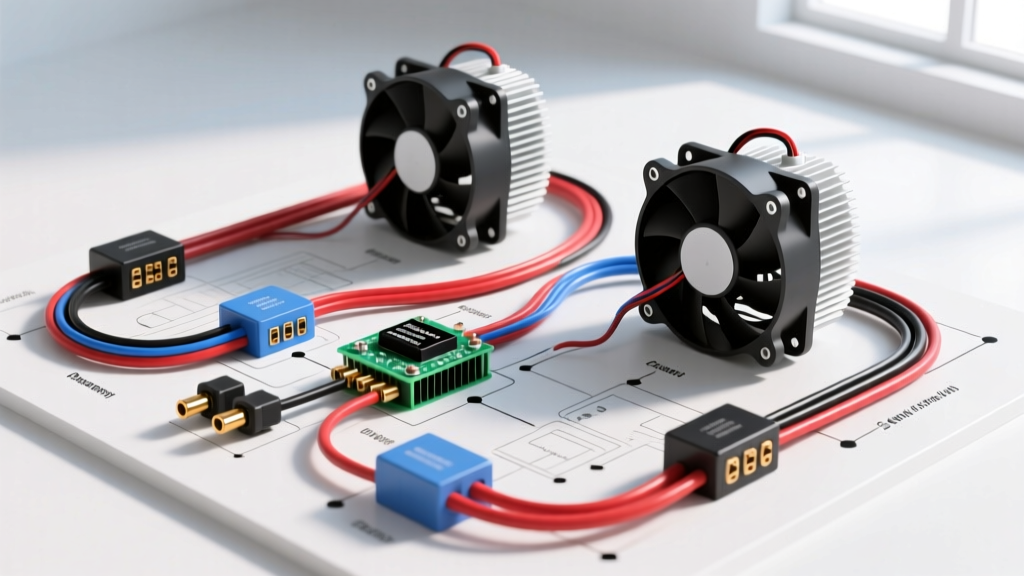
Why Upgrade to a Dual High-CFM Electric Fan Setup?
Swapping from a mechanical clutch fan or a weak stock single electric fan to a high-performance dual electric setup is one of the most effective cooling and horsepower modifications you can perform on a muscle car, truck, or track vehicle. By eliminating parasitic drag on the water pump pulley, you free up anywhere from 8 to 15 rear-wheel horsepower while gaining precise, temperature-based cooling control. However, dual high-CFM fans (such as 11-inch Spal or Flex-a-lite units) draw massive electrical current. Understanding the wiring diagram of fan relay systems is critical to prevent melted harnesses, severe voltage drop, and catastrophic PWM controller failure.
According to Flex-a-lite engineering guidelines, a single high-performance 11-inch S-blade fan can draw up to 18 amps continuously, with inrush currents exceeding 35 amps upon startup. When running a dual fan setup, your electrical system must be engineered to handle 60+ amps of transient load without sagging below 12.5 volts at the relay coils.
Alternator Capacity & Electrical Load Calculations
Before fabricating your harness, verify your alternator's output. A standard GM CS130 or Ford 3G 95-amp alternator will easily be overwhelmed if you are also running an electric fuel pump, MSD ignition, and aftermarket headlights. For a dual 2800-CFM fan upgrade, we recommend a minimum 140-amp alternator (such as a Denso SC14 upgrade or a Powermaster Street/Strip unit).
Fan Amperage & Wire Gauge Sizing Chart
Adhering to SAE J1128 Low Tension Primary Cable standards, wire gauge must be selected based on continuous amperage and harness length. Voltage drop over long engine bay runs is the number one cause of slow-spinning fan motors.
| Wire Segment | Max Continuous Load | Min AWG (Under 10ft) | Min AWG (Over 10ft) | Fuse Rating |
|---|---|---|---|---|
| Main Battery Feed | 50A | 8 AWG | 6 AWG | 60A Mega Fuse |
| Relay to Fan Motor | 25A (per fan) | 10 AWG | 8 AWG | 30A ATO (per leg) |
| Controller Trigger | 2A | 16 AWG | 14 AWG | 5A Mini Fuse |
| Relay Coil Ground | 0.5A | 14 AWG | 14 AWG | N/A |
The Dual Electric Fan Wiring Diagram of Fan Relay Systems
When analyzing the wiring diagram of fan controller upgrades, you must separate the high-amperage power circuit from the low-amperage control circuit. Relying on a thermostat switch or PWM module to directly carry the fan's amperage will instantly melt the internal MOSFETs or switch contacts. We utilize two 40A Bosch-style ISO Mini Relays (Part #0 332 014 150) to handle the heavy lifting. For comprehensive relay specifications, refer to the Bosch Automotive Relays catalog.
Pinout Configuration for Bosch-Style ISO Relays
| Relay Pin | Function | Wire Color | Wire Gauge | Destination |
|---|---|---|---|---|
| Pin 30 | High-Amp Power In | Red | 10 AWG | Fan Motor (+) Terminal |
| Pin 87 | High-Amp Power Out | Blue | 10 AWG | 60A Mega Fuse to Battery (+) |
| Pin 85 | Coil Ground | Black | 14 AWG | Clean Chassis Ground / Engine Block |
| Pin 86 | Coil Trigger (+) | Yellow | 14 AWG | PWM Controller Fan Output |
Note: In this specific harness layout, Pin 87 receives power from the battery, and Pin 30 sends it to the fan. While ISO relays are bidirectional, wiring the battery to 87 and the load to 30 ensures the internal suppression resistor (if equipped) correctly clamps back-EMF spikes.
Step-by-Step Harness Fabrication & Back-EMF Protection
Upgrading to a Pulse Width Modulation (PWM) fan controller (like the Davies Craig Digital Fan Controller) allows the fans to ramp up smoothly from 40% to 100% speed based on coolant temp. However, PWM controllers are highly sensitive to inductive kickback (Back-EMF).
Installing Flyback Diodes
When the PWM controller cuts power to the relay coil (Pin 86), the collapsing magnetic field inside the relay generates a high-voltage spike that travels backward into the controller's circuitry, often destroying it. To prevent this:
- Solder a 1N4007 rectifier diode across the relay socket wires for Pin 85 and Pin 86.
- The silver stripe on the diode must point toward the Pin 86 (Trigger +) wire.
- This creates a closed loop that safely dissipates the voltage spike back into the relay coil rather than sending it to your expensive PWM module.
Terminal Crimping and Weatherproofing
Do not rely on cheap crimp connectors for high-amperage cooling fan circuits. Use a ratcheting hex-crimp tool for all 10 AWG and 8 AWG ring terminals. At the fan motor connection, the engine bay environment guarantees exposure to water, road salt, and extreme heat. Strip back the wire, slide on a piece of dual-wall adhesive-lined heat shrink, crimp a Deutsch DT 2-pin connector, and apply heat until the adhesive oozes from the ends. This provides an IP67 waterproof seal that prevents the green corrosion commonly seen on exposed spade terminals.
Routing, Grounding, and Thermal Management
The physical routing of your wiring diagram of fan harnesses is just as important as the electrical schematic.
- Away from Exhaust: Never route 10 AWG power wires within 6 inches of exhaust headers. Even with high-temp cross-linked polyethylene (XLPE) insulation, radiant heat will melt standard PVC primary wire.
- Split-Loom Protection: Encase all harness runs in nylon split-loom tubing and secure them every 8 inches with UV-resistant zip ties or aluminum Adel clamps.
- The Ground Path: A 40A relay is only as good as its ground. Do not ground the relay coils to the radiator support, which often has poor conductivity due to paint and rubber bushings. Run a dedicated 14 AWG black wire to a clean, bare-metal point on the engine block or cylinder head, secured with a stainless steel bolt and star washer. Apply dielectric grease over the terminal to prevent galvanic corrosion.
Troubleshooting Common Fan Upgrade Failures
Even with a perfect schematic, real-world variables can cause issues. Use this diagnostic tree to troubleshoot your dual fan upgrade:
| Symptom | Probable Cause | Multimeter Test & Fix |
|---|---|---|
| Fans spin slowly / lack CFM | Severe voltage drop on power feed | Test voltage at Fan (+) terminal while running. If below 12.8V, upgrade to 8 AWG wire or clean battery terminals. |
| PWM Controller burns out | Missing flyback diode on relay coil | Inspect relay harness. Solder 1N4007 diode across pins 85/86. Replace damaged controller. |
| Relay clicks rapidly (chatters) | Undersized trigger wire or bad ground | Check voltage at Pin 86 during cranking. If it drops below 9V, run a dedicated 12V ignition trigger instead of a tapped sensor wire. |
| One fan runs, other does not | Blade bind or blown inline ATO fuse | Check 30A inline fuse. Manually spin fan blades to check for debris or seized motor bearings. |
Final Verification Steps
Before starting the engine, perform a dry-run test. Disconnect the PWM temperature sensor and use a potentiometer or the controller's manual override switch to command the fans to 100%. Use a digital multimeter to measure the voltage drop across the main Mega Fuse and the relay contacts. A healthy circuit should show less than 0.2V drop across the entire high-amperage path. Once verified, secure all loom, apply heat shrink to all splices, and enjoy the reliable, parasitic-free cooling of your upgraded dual fan setup.