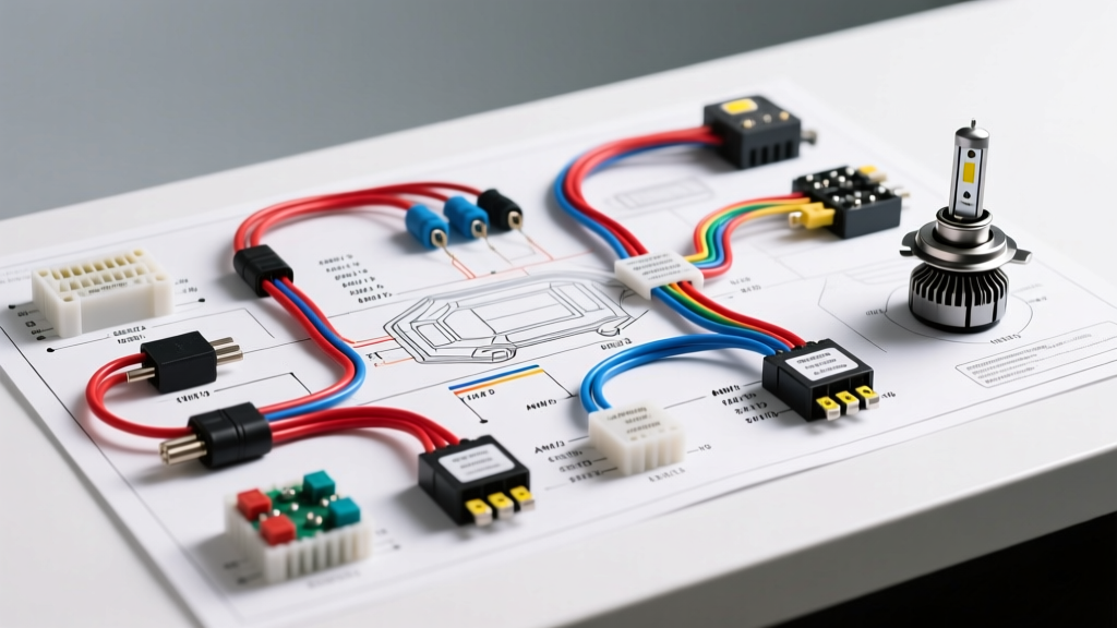
Why Factory Headlamp Wiring Fails Modern Upgrades
When planning a high-performance lighting upgrade, enthusiasts often overlook the most critical component: the vehicle's factory wiring harness. Most OEM headlamp circuits were designed in the 1990s and early 2000s to power standard 55W/60W halogen bulbs. These factory circuits typically utilize 18 AWG or even 20 AWG wire, routed through a complex network of switches, relays, and multiplexed control modules.
While an 18 AWG wire can technically handle the 4.5 to 5.0 amps required by a halogen bulb, the distance from the battery to the front fascia (often exceeding 12 feet) introduces significant voltage drop. By the time the current reaches the headlamp connector, a 14.4V system may only be delivering 12.8V. When you upgrade to high-draw HID ballasts or LED matrices with heavy inrush currents, this voltage drop exacerbates, leading to melted plastic connectors, flickering, and premature bulb failure. To achieve maximum lumen output and reliability, bypassing the factory power delivery is mandatory. This custom car headlamp wiring diagram outlines the industry-standard relay-based harness modification required for safe, high-output lighting upgrades.
The Ultimate Car Headlamp Wiring Diagram for Relay Upgrades
The core of any professional lighting upgrade is the 'relay harness.' This setup uses the factory headlamp plug strictly as a low-amperage trigger signal to switch a heavy-duty relay, which then pulls power directly from the vehicle's battery. Below is the schematic logic and physical routing for a dual-headlamp relay upgrade.
Standard 4-Pin ISO Relay Pinout Configuration
Automotive lighting upgrades rely on the standard Bosch-style 4-pin ISO mini relay. Understanding the pinout is critical for correctly wiring the harness and avoiding dead shorts.
| Relay Pin | Function | Wire Color | Wire Gauge (AWG) | Routing Destination |
|---|---|---|---|---|
| 30 | Power In (Constant) | Red | 10 AWG (TXL) | Battery Positive (+) via Inline Fuse |
| 87 | Power Out (Switched) | Red | 12 AWG (TXL) | Left & Right Headlamp Positive Terminals |
| 85 | Coil Ground | Black | 14 AWG (TXL) | Chassis Ground Point |
| 86 | Coil Trigger (Switched) | Blue | 16 AWG (TXL) | Factory Headlamp Plug Positive Wire |
Wire Gauge (AWG) and Fuse Sizing for High-Output Lamps
Selecting the correct wire gauge and fuse rating is governed by SAE International standards for automotive electrical systems. Using undersized wire creates a fire hazard, while oversized wire makes routing through the firewall and engine bay unnecessarily difficult. We recommend using SAE J1128 TXL (Thermoplastic Cross-Linked) wire, which features a thin, high-temperature insulation layer perfect for tight engine bays.
| Wire Gauge (AWG) | Max Amperage (Chassis Wiring) | Recommended Fuse Size | Application in Headlamp Harness |
|---|---|---|---|
| 10 AWG | 30 Amps | 25A or 30A ATO | Main battery feed to Relay Pin 30 |
| 12 AWG | 20 Amps | 15A or 20A ATO | Relay Pin 87 to Headlamp Pigtails |
| 14 AWG | 15 Amps | N/A (Protected by main) | Relay Coil Ground (Pin 85) |
| 16 AWG | 10 Amps | N/A (Protected by OEM) | Trigger Wire from Factory Plug (Pin 86) |
Expert Note on Fusing: The main inline ATO/ATC blade fuse must be installed within 18 inches of the battery positive terminal. If the wire chafes against the radiator support or engine block before the fuse, it will cause an unfused dead short, leading to an electrical fire. For dual-relay setups (one relay per headlamp), use two separate 15A fuses rather than a single 30A fuse on a shared power line to maintain redundancy.
Step-by-Step Headlamp Harness Modification Guide
1. Upgrading the Headlamp Pigtails
Factory plastic headlamp connectors (especially H4/9003 and H7 styles) are notorious for melting due to terminal oxidation and increased electrical resistance. Before connecting your new relay harness, cut off the OEM plastic plugs and solder on ceramic headlamp pigtails. Ceramic housings withstand temperatures exceeding 400°F and will not melt, even if a high-draw LED driver experiences a thermal fault. Use adhesive-lined marine-grade heat shrink (3:1 shrink ratio) over the solder joints to prevent moisture ingress and copper oxidation.
2. Routing the Main Power and Ground
Route the 10 AWG red power wire from the battery along the existing factory wiring loom. Secure the wire every 12 inches using UV-resistant nylon zip ties or P-clips. Avoid routing wires near the exhaust manifold or sharp, unpainted metal edges. For the relay ground (Pin 85), locate a factory chassis ground bolt in the engine bay. Remove the bolt, sand the contact area down to bare metal using 80-grit sandpaper, attach a 5/16-inch closed-loop ring terminal, and coat the connection with dielectric grease before tightening to the manufacturer's torque specification (typically 10-15 lb-ft).
3. Tapping the Trigger Wire
The trigger wire (Pin 86) tells the relay when to turn on. Tap into the factory low-beam positive wire. Never use 'scotch-lock' or T-tap connectors. These pierce the wire insulation, exposing the copper strands to water and causing galvanic corrosion, which eventually leads to an open circuit. Instead, use a Posi-Tap connector or carefully strip a 1/2-inch window in the factory wire insulation, solder the 16 AWG trigger wire to it, and seal it with dual-wall heat shrink.
Overcoming PWM and CANbus Errors in Modern Vehicles
If you are applying this car headlamp wiring diagram to a vehicle manufactured after 2010 (such as late-model Dodge Rams, Jeep Wranglers, or European platforms), you will likely encounter Pulse Width Modulation (PWM) or CANbus bulb-out warnings. Modern TIPM (Totally Integrated Power Modules) do not send a steady 12V signal to the headlights. Instead, they pulse the voltage rapidly to monitor circuit resistance and detect blown bulbs.
Because LED and HID ballasts draw current differently than a resistive halogen filament, the vehicle's computer interprets the load as a 'blown bulb' and cuts power entirely, resulting in severe flickering or the lights shutting off after three seconds.
The PWM Decoder Solution
To solve this, you must install a PWM decoder or a large electrolytic capacitor (typically 4700µF to 10000µF, rated at 25V) inline on the trigger wire between the factory plug and Relay Pin 86. The capacitor acts as a buffer, absorbing the rapid pulses and releasing a steady, smooth DC voltage to the relay coil. Alternatively, you can purchase plug-and-play CANbus anti-flicker modules that integrate this capacitor circuit into a weatherproof housing, as detailed in advanced lighting guides by experts like Daniel Stern Lighting.
Troubleshooting Common Upgrade Wiring Faults
Even with a flawless schematic, physical installation errors can cause system failures. Use this diagnostic tree to resolve common headlamp upgrade issues:
- Symptom: Headlamps do not turn on, relay does not click.
Cause: Missing ground or no trigger signal.
Fix: Use a multimeter to test for 12V between the factory trigger wire and the battery negative terminal with the headlights switched on. If 12V is present, check the continuity of the relay ground wire (Pin 85) to the chassis. - Symptom: Headlamps flicker rapidly when the engine is running.
Cause: Alternator ripple current or PWM signal on the trigger line.
Fix: Install a PWM filter/capacitor on the trigger wire. Ensure the main battery power wire is connected directly to the battery post, not to a noisy accessory terminal on the fuse box. - Symptom: One headlamp is dimmer than the other.
Cause: Voltage drop on the switched power side or a poor ground at the headlamp itself.
Fix: Perform a voltage drop test. Place your multimeter's positive probe on the battery positive terminal and the negative probe on the headlamp's positive terminal while the lights are on. A reading higher than 0.2V indicates excessive resistance in the wire, crimps, or relay contacts. Upgrade the wire or replace the crimp terminals. - Symptom: The main 30A fuse blows immediately upon connection.
Cause: Dead short in the 10 AWG power wire or internal relay failure.
Fix: Disconnect the relay. Check the 10 AWG wire for pinched insulation against the radiator core support or strut tower. Inspect the relay socket for bent pins causing Pin 30 and Pin 87 to bridge internally.
Final Verification and Testing
Before securing the harness permanently and reassembling the front fascia, perform a 30-minute burn-in test. Turn the headlamps on and use an infrared thermometer to check the temperature of the relay casing, the inline fuse holder, and the ceramic headlamp pigtails. If any component exceeds 140°F (60°C), you have excessive resistance in that specific node, usually caused by a poorly crimped terminal. For high-end builds, reference comprehensive harness schematics from manufacturers like Painless Performance Products to ensure your routing and loom wrapping meet professional motorsport standards. A properly executed relay harness will not only protect your vehicle's factory wiring but will deliver maximum voltage to your new lamps, ensuring the brightest, safest night driving experience possible.