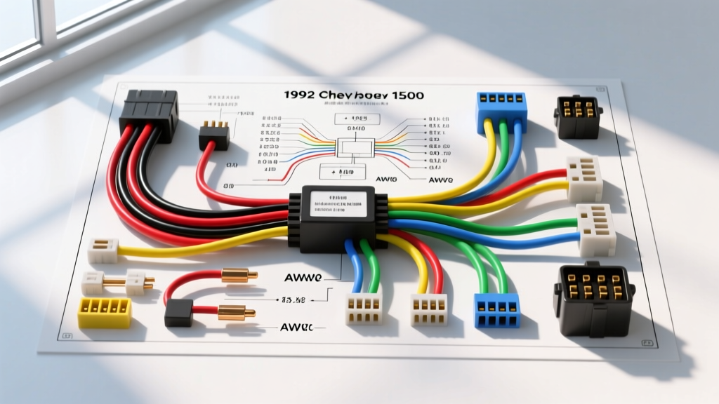
Understanding the 1992 Chevy 1500 Ignition Wiring Diagram
If you are diving into the electrical system of a GMT400 platform truck, the 1992 Chevy 1500 ignition wiring diagram is one of the most critical schematics you will encounter. For beginners, automotive wiring can feel like an intimidating maze of copper and plastic. However, General Motors designed the C/K 1500 series with a relatively straightforward, logical electrical architecture. By breaking down the ignition switch circuits, understanding the wire color codes, and learning how to test the system with a digital multimeter (DMM), you can diagnose no-start conditions, accessory power losses, and stalling issues with confidence.
Before touching a single wire, it is vital to understand a common point of confusion for novice mechanics: the difference between the ignition lock cylinder and the ignition switch. The lock cylinder is the mechanical tumbler on the steering column where you insert your key. The actual electrical ignition switch is a separate component mounted much further down the steering column, near the brake pedal support bracket. When you turn the key, a metal actuator rod (or rack gear) pushes down the column to physically slide the contacts inside the electrical switch. This mechanical linkage is the root cause of many 'electrical' problems on the 1992 C1500.
Decoding the GMT400 Ignition Switch Pinout
The primary ignition switch connector on the 1992 Chevrolet 1500 is typically a 4-pin or 5-pin flat rectangular harness plug. This switch acts as the main power distribution gatekeeper for the truck. It takes heavy-duty constant 12V power directly from the battery and routes it to the accessory buses, the Engine Control Module (ECM), the High Energy Ignition (HEI) distributor, and the starter solenoid.
Below is the definitive reference table for the primary ignition switch harness. This data aligns with OEM GM service documentation and standard SAE J1128 low-tension primary cable specifications.
| Pin / Circuit | OEM Wire Color | AWG Size | Circuit Function | Active Key Position |
|---|---|---|---|---|
| Pin A (BAT) | Thick Red | 10 AWG | Constant Battery Feed (Main Power In) | Constant (All Positions) |
| Pin B (ACC) | Brown | 12 AWG | Accessory Power (Radio, Wipers, HVAC) | ACC and RUN |
| Pin C (IGN 1) | Pink | 12 AWG | Ignition Run Feed (ECM, HEI, Dash, Fuel Pump) | RUN and START |
| Pin D (CRANK) | Purple | 12 AWG | Starter Solenoid Engage Signal | START Only |
Why Wire Gauge Matters in the Ignition Circuit
Notice that the Battery Feed (Red) wire is 10 AWG, while the output circuits are 12 AWG. The 10 AWG red wire must handle the combined amperage draw of the HVAC blower motor, the main accessory fuse block feeds, and the ignition buses. It is not uncommon for this wire to see 30 to 40 amps of continuous load when the AC and headlights are on. Using a smaller gauge wire or a cheap, undersized replacement pigtail will result in severe voltage drop, melted plastic connector housings, and potential electrical fires.
The Crank Circuit: Purple Wire and the Neutral Safety Switch
Beginners often assume the purple crank wire runs directly from the ignition switch to the starter solenoid. On a 1992 Chevy 1500, this is incorrect. The purple wire first routes to the Neutral Safety Switch (NSS) (located on the steering column under the dash for automatic transmissions, or the clutch pedal position switch for manual transmissions).
When you turn the key to the START position, 12V travels down the purple wire, passes through the closed contacts of the NSS (only when in Park or Neutral), and then continues to the 'S' terminal on the starter solenoid. If your truck has a 'no-crank' condition but the dash lights stay bright, do not immediately condemn the ignition switch or the starter. Backprobe the purple wire at the ignition switch to verify 12V is leaving the switch, then check for 12V on the solenoid side of the NSS.
Beginner Multimeter Testing Guide
To properly diagnose the 1992 Chevy 1500 ignition wiring diagram, you need a Digital Multimeter (DMM). Avoid using cheap test lights, as they can draw enough current to damage sensitive ECM circuits or give false positives on high-resistance connections.
- Voltage Drop Testing (The Professional Method): Set your DMM to DC Volts. Place the red probe on the battery positive terminal and the black probe on the Pink (IGN 1) wire at the switch connector (using a backprobe pin). Turn the key to RUN. A reading of more than 0.2V indicates high resistance inside the switch contacts or a corroded bulkhead connector.
- Continuity Testing (Power Off): Disconnect the battery negative terminal. Set the DMM to Ohms/Continuity. Probe the Red (BAT) and Pink (IGN 1) terminals on the switch side. Turn the key to RUN. You should see near 0.00 Ohms. If the reading fluctuates or shows 'OL' (Open Loop), the internal copper contacts are burned or the mechanical actuator rod is out of adjustment.
Common GMT400 Ignition Failure Modes
The 1992 C/K 1500 is a legendary truck, but its ignition system has a few well-documented failure points that every owner should know how to identify.
1. Melted Pigtail Connectors
Because the 10 AWG red wire carries high amperage, any slight corrosion or loose terminal crimp creates resistance. Resistance generates heat. Over time, this heat melts the plastic housing of the ignition switch pigtail, causing the Red and Brown wire terminals to push backward out of the connector. The Fix: Never simply push the terminals back in. You must cut out the melted connector and splice in a new, high-temperature ceramic or heavy-duty GM OEM replacement pigtail (such as those sourced via Helm Incorporated service manuals and parts catalogs). Always use adhesive-lined marine heat shrink and a proper ratcheting crimp tool.
2. Engine Dies When Key Returns to RUN
Symptom: The truck cranks and fires up while you hold the key in the START position, but the moment you release the key and it springs back to the RUN position, the engine instantly dies.
Cause: The Pink (IGN 1) wire circuit is failing. In the START position, the switch sends power to the HEI distributor and ECM. When you release the key, the internal slider must maintain contact on the IGN 1 bus. If the internal contacts are worn, or if the mechanical actuator rod has excessive play, the Pink circuit drops to 0V, killing the spark and fuel injectors.
3. Starter Stays Engaged (Run-On)
Symptom: You release the key from START, but the starter continues to grind against the flywheel.
Cause: Either the ignition switch's internal spring has failed (welding the purple wire contacts together), or the Purple wire is shorted to a constant 12V source somewhere in the column harness. Immediately disconnect the battery negative cable to save the starter motor and flywheel ring gear, then inspect the column harness for chafing against the steel steering column tube.
Mechanical Adjustment: The Hidden Secret
Because the 1992 Chevy 1500 ignition switch is mounted on the column and pushed by a rod, it requires physical adjustment. The switch housing features two elongated slots secured by Torx screws. If the switch is mounted too high or too low, the key positions will not align with the internal electrical contacts. This can result in the truck cranking while in gear (bypassing the neutral safety switch) or the key feeling 'loose' and failing to engage the starter. Loosening these screws and sliding the switch slightly up or down the column is the final, crucial step in any ignition wiring repair on the GMT400 platform.