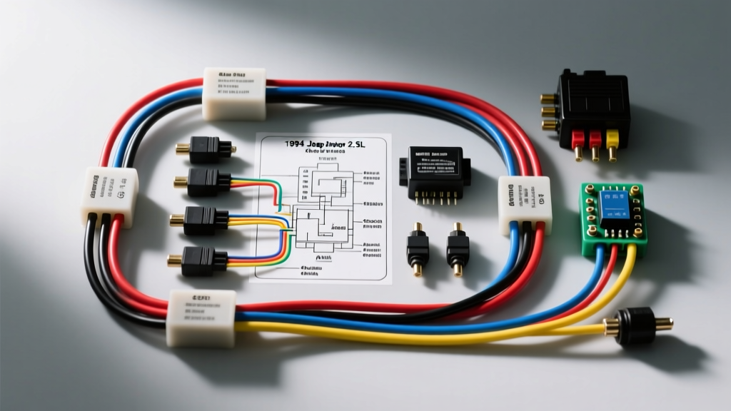
1994 Jeep Wrangler 2.5L MPI System Architecture
The 1994 Jeep Wrangler (YJ generation) equipped with the 2.5L AMC inline-4 engine utilizes a Multi-Port Fuel Injection (MPI) system. Unlike the earlier Throttle Body Injection (TBI) setups, this MPI configuration requires precise sequential or batch-fire pulsing of four individual high-impedance injectors. When referencing a 1994 Jeep Wrangler 2.5 fuel injectors wiring diagram, it is critical to understand that the injectors do not receive constant battery voltage. Instead, they rely on the Automatic Shutdown (ASD) relay for switched 12V power, while the Powertrain Control Module (PCM) manages the ground path via internal saturation-style drivers.
OEM Wiring Schematic Overview
The injector circuit is divided into two primary halves: the power feed circuit and the PCM ground control circuit. Both circuits must be intact for the engine to start and run. Below is the logical flow of the wiring harness from the Power Distribution Center (PDC) to the injector rail.
1. ASD Relay Power Feed Circuit
The ASD relay is located in the engine compartment Power Distribution Center (PDC). When the ignition is turned to the 'ON' position and the PCM detects crankshaft position sensor (CPS) pulses, the PCM grounds the ASD relay coil. This closes the relay contacts, sending battery voltage to the fuel injectors, ignition coil, and oxygen sensor heaters.
- Power Source: Fused B+ from the PDC (typically a 20A or 30A fuse).
- Relay Output Wire: Dark Green with Black tracer (DG/BK).
- Harness Routing: The DG/BK wire exits the PDC, travels through the main engine harness, and splices internally near the firewall to feed all four injector connectors in parallel.
- Wire Gauge: 14 AWG for the main ASD feed, stepping down to 18 AWG at the injector splice points.
2. PCM Ground Control & 60-Way Connector Pinout
The 1994 YJ 2.5L utilizes a Chrysler 60-way PCM connector. The PCM completes the injector circuit by grounding the control side of the injector solenoid. The internal drivers are current-limiting saturation switches designed for high-impedance injectors.
| Injector Cylinder | PCM Connector Cavity | OEM Wire Color | Circuit Function |
|---|---|---|---|
| Cylinder 1 | Pin 3 | Brown / White (BR/WT) | Injector 1 Driver Ground |
| Cylinder 2 | Pin 4 | Brown / Yellow (BR/YL) | Injector 2 Driver Ground |
| Cylinder 3 | Pin 5 | Brown / Black (BR/BK) | Injector 3 Driver Ground |
| Cylinder 4 | Pin 6 | Brown / Red (BR/RD) | Injector 4 Driver Ground |
Note: Always verify pin cavities using a digital multimeter (DMM) against your specific VIN, as mid-year production changes in Chrysler's SBEC/JTEC transition can occasionally shift pin assignments by one cavity.
Injector Specifications & Electrical Testing
Proper diagnostics require knowing the exact electrical parameters of the OEM Bosch-style injectors used in the 1994 2.5L engine. According to SAE J1128 standards for low-tension primary cables, the 18 AWG TXL (cross-linked polyethylene) wire used in this harness is rated for high-temperature engine bay environments, but the injector solenoids themselves must be tested for internal degradation.
| Parameter | Specification | Diagnostic Tolerance |
|---|---|---|
| Solenoid Type | High-Impedance (Saturated Switch) | N/A |
| Coil Resistance (at 68°F / 20°C) | 14.0 - 15.5 Ohms | Replace if < 11.0 or > 18.0 Ohms |
| Operating Voltage | 12.0V - 14.5V (Switched via ASD) | Must not drop below 10.5V during cranking |
| Connector Type | EV1 / Jetronic (2-Pin) | Check for spread terminals |
| Harness Wire Gauge | 18 AWG (TXL Insulation) | Do not repair with standard PVC wire |
Oscilloscope Waveform Analysis
When using an automotive oscilloscope to probe the control wire (e.g., the BR/WT wire on Pin 3) with the engine idling, you should observe a classic saturation waveform:
- Key On, Engine Off: The scope will read battery voltage (~12.4V) because the ASD relay is energized but the PCM driver is open.
- Injector On-Time: The voltage drops sharply to near 0V (typically 0.8V to 1.2V) as the PCM grounds the circuit.
- Injector Off-Time (Inductive Kickback): When the PCM opens the ground circuit, the collapsing magnetic field inside the injector solenoid generates a voltage spike. Expect to see a peak between 45V and 65V, followed by a rapid decay.
If the inductive spike is missing, the injector coil is likely open internally, or there is a break in the 18 AWG harness wire between the PCM and the injector rail.
Diagnostic Decision Tree: Common Wiring Faults
Use this structured troubleshooting guide to isolate faults in the 1994 Jeep Wrangler 2.5 fuel injectors wiring diagram.
Symptom: Engine Cranks But Will Not Start (No Injector Pulse)
- Step 1: Check ASD Relay Output. Probe the DG/BK wire at any injector connector with a test light or DMM during cranking.
- If NO voltage: The ASD relay is not engaging. Check the CPS (Crankshaft Position Sensor) signal. The PCM will not ground the ASD relay without a valid CPS signal. Refer to Haynes Jeep Wrangler Repair Manuals for CPS testing procedures.
- If 12V is present: Proceed to Step 2.
- Step 2: Check Injector Ground Pulse. Connect a NOID light to the injector harness connector. Crank the engine.
- If NOID light flashes: The wiring harness and PCM are functioning perfectly. The issue is mechanical (fuel pressure, clogged injectors, or timing).
- If NOID light does NOT flash: Proceed to Step 3.
- Step 3: Continuity Test to PCM. Disconnect the battery and the PCM 60-way connector. Measure resistance from the injector control wire (e.g., BR/WT) to the corresponding PCM cavity (Pin 3).
- If resistance is > 1.0 Ohm: You have an open circuit in the engine harness. Look for chafing near the valve cover or corrosion in the intermediate bulkhead connector.
- If resistance is < 1.0 Ohm: The wiring is intact. The internal PCM driver has likely failed, requiring PCM replacement or professional rebuilding.
Symptom: Random Misfire & Lean Codes (P0171)
- Cause: Voltage drop across corroded injector connectors or failing ASD relay contacts.
- Fix: Perform a voltage drop test across the injector power feed. Place one DMM lead on the battery positive terminal and the other on the injector power pin (DG/BK). With the engine running, a voltage drop greater than 0.3V indicates high resistance. Clean the PDC ASD relay terminals and inspect the injector harness for brittle insulation, which is common on 1990s YJ Wranglers exposed to extreme under-hood heat cycles. Ensure any replacement pigtails conform to USCAR automotive connector standards to prevent moisture ingress and terminal fretting.
Harness Repair Best Practices
When repairing the 18 AWG injector control wires on the 1994 2.5L, never use standard twist-on wire connectors or electrical tape. The engine bay environment requires solder-seal heat shrink butt connectors. Because the PCM drivers are sensitive to resistance changes, a poor splice can alter the current draw, potentially causing the PCM to set a false injector circuit fault code or, in worst-case scenarios, damaging the internal driver transistor. Always route repaired wires away from the exhaust manifold and secure them with high-temperature Tesa tape or split loom tubing.