The Hidden Dangers of 48V DC Golf Cart Systems
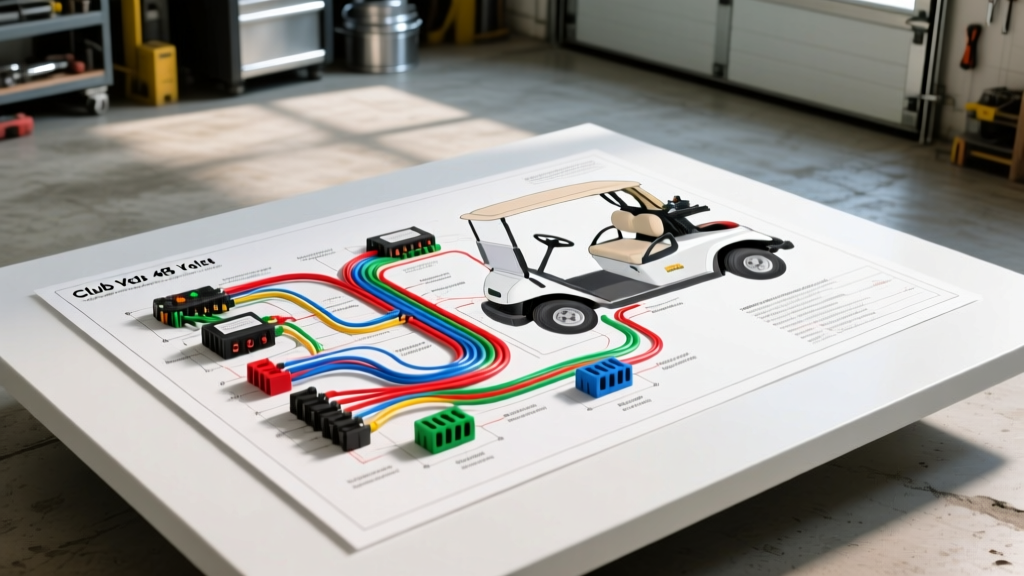
When enthusiasts and mechanics search for a club car wiring diagram 48 volt pdf, they are typically preparing for an aftermarket motor upgrade, an MCOR (Motor Controller Operator Request) replacement, or troubleshooting a stubborn solenoid click. While a wiring schematic provides the roadmap, it rarely highlights the severe safety hazards inherent to 48V DC architecture.
A nominal 48V lead-acid battery pack actually rests at 50.4V and peaks at 57.6V when fully charged. Unlike alternating current (AC), direct current (DC) does not have a zero-crossing point. If a connection arcs under load, the DC arc will sustain itself, generating temperatures exceeding 10,000°F. This can instantly melt copper, ignite battery hydrogen gas, or weld solenoid contacts shut, causing a runaway vehicle. Understanding the physical realities of your cart's electrical system is just as critical as reading the diagram.
Top 5 Critical Mistakes When Using a 48V Wiring Diagram
Even seasoned automotive technicians make mistakes when transitioning from 12V internal combustion vehicles to 48V electric drivetrains. Here are the most common and dangerous errors made when following a Club Car 48V schematic.
Mistake 1: Omitting the Pre-Charge Resistor
Modern 48V controllers (both OEM Club Car IQ/Excel and aftermarket units like Alltrax or Navitas) utilize massive internal capacitor banks to smooth out DC ripple. If you wire the main B+ directly to the controller without a pre-charge circuit, the initial inrush current can exceed 800 amps for a fraction of a second. This will instantly weld the main solenoid contacts or blow the controller's internal MOSFETs.
- The Fix: Always install a 250-Ohm, 10-Watt ceramic pre-charge resistor across the large terminals of the main solenoid. This allows the capacitors to charge slowly before the solenoid fully engages the main high-amperage circuit.
Mistake 2: Reversing the Flyback Diode
The small terminals on the HD (Heavy Duty) solenoid control the electromagnetic coil. When the controller cuts power to this coil, the collapsing magnetic field generates a massive reverse voltage spike (flyback voltage) that can exceed 200V. The flyback diode bleeds this spike safely back into the circuit.
- The Fix: The diode must be installed with the silver stripe facing the B+ (positive) side. Reversing the diode creates a direct dead short across the solenoid coil the moment the key switch is turned on, instantly frying the controller's low-side driver circuit.
Mistake 3: Undersizing Main Power Cables
Standard automotive wire is rated for 12V systems where voltage drop is less critical over short distances. A 48V golf cart motor can draw 350+ amps under heavy load or hill climbs. Using 4 AWG wire for the main battery and motor leads will result in severe voltage sag, overheating, and melted insulation.
- The Fix: Main battery cables, motor leads, and solenoid jumpers must be 1 AWG or 2 AWG fine-strand, high-flexibility copper wire, compliant with SAE J1128 standards for low-tension primary cable.
Mistake 4: Bypassing the Tow/Run Switch
Many DIYers bypass the Tow/Run switch when it fails, assuming it is merely a safety interlock. In reality, this switch cuts power to the controller's logic board and disables the regenerative braking (rollaway protection) circuit. Bypassing it leaves the controller in a perpetual "Run" state, which will drain the battery pack to zero and cause thermal runaway in the MOSFETs during charging.
Mistake 5: Misinterpreting MCOR vs. V-Glide Wiring
Older Club Car DS models used a resistive V-Glide (potentiometer), while the IQ and Excel systems use an inductive MCOR. Connecting an MCOR using a V-Glide wiring diagram will send incorrect voltage signals to the controller, resulting in sudden, uncommanded acceleration or an immediate high-pedal fault code (HPD).
Club Car IQ 48V Controller Pinout & Specification Chart
When referencing your 48V PDF diagram, cross-check your physical harness against this OEM specification table. Incorrect pin assignments are the leading cause of controller death.
| Pin | Wire Color (OEM) | AWG | Function | Torque Spec / Note |
|---|---|---|---|---|
| 1 | Red | 12 AWG | B+ (Battery Positive Logic) | Fused inline (15A) |
| 2 | Blue | 14 AWG | Solenoid Coil Return | Connects to Solenoid small terminal |
| 3 | Yellow | 12 AWG | 48V Switched Output | Key switch / OBC input |
| 4 | White | 16 AWG | Throttle Signal High | MCOR Pin 2 (0.8V - 3.3V sweep) |
| 5 | White/Black | 16 AWG | Throttle Signal Low / Ref | MCOR Pin 1 |
| 6 | Green | 16 AWG | Forward Microswitch Input | F&R Switch validation |
| 7 | Green/White | 16 AWG | Reverse Microswitch Input | F&R Switch validation |
| 8 | Black | 12 AWG | B- (Battery Negative Logic) | Controller ground reference |
Essential Safety Protocols Before Touching the Controller
Never rely solely on the key switch or the Tow/Run switch to isolate power. Follow this strict lockout/tagout procedure before cutting, crimping, or testing any 48V Club Car wiring.
- Set to TOW: Flip the Tow/Run switch under the passenger seat to the "TOW" position. This disables the rollaway protection and wakes up the OBC (On-Board Computer) for sleep mode.
- Disconnect the Main Negative: Using a 1/2-inch insulated wrench, remove the main negative cable from the battery pack's negative terminal. Warning: Never disconnect the positive side first; a dropped wrench across the positive terminal and the cart's chassis will cause an immediate arc flash.
- Capacitive Discharge: Even with the battery disconnected, the controller's internal capacitors hold a lethal charge. Connect a 100-Ohm, 50-Watt discharge resistor across the main B+ and B- controller studs for 60 seconds. Verify with a digital multimeter (DMM) that voltage reads below 2V before touching any terminals.
- Inspect for Hydrogen Damage: While the pack is open, inspect the battery hold-down straps and nearby wiring harnesses for white, powdery corrosion. Sulfuric acid off-gassing destroys copper strands from the inside out, increasing resistance and creating localized heat spots.
Upgrading to Lithium (LiFePO4): Diagram Alterations
If your wiring project involves converting from lead-acid to a 48V LiFePO4 battery pack, the standard Club Car PDF diagram requires modifications. Lithium Battery Management Systems (BMS) require specific communication protocols to prevent the OBC from over-discharging the cells. You must install a BMS-to-OBC communication harness or an OBC bypass module. Furthermore, LiFePO4 packs can deliver sustained amperage far exceeding lead-acid; upgrading the main solenoid to a 600A continuous-duty aircraft contactor (such as an Albright SW200) and utilizing 1/0 AWG welding cable is highly recommended to prevent voltage sag under peak torque demands.
Authoritative Resources & Standards
Always ensure your wiring materials and practices align with established automotive and electrical safety standards. For deeper technical validation, refer to the following resources:
- SAE J1128: Standard for Low Tension Primary Cable, defining insulation thickness and thermal ratings for automotive and EV wiring. (SAE International)
- NFPA 70E: Standard for Electrical Safety in the Workplace, specifically the sections detailing DC arc flash boundaries and PPE requirements for voltages exceeding 50V DC. (National Fire Protection Association)
- Club Car Support & Manuals: Official OEM service documentation and wiring schematics for IQ, Excel, and Onward platforms. (Club Car Official Support)
By combining the visual roadmap of your 48V wiring diagram with these critical safety protocols and specification standards, you ensure a reliable, high-performance, and most importantly, safe electrical system for your vehicle.