Introduction to Carling Contura Switches in Automotive Applications
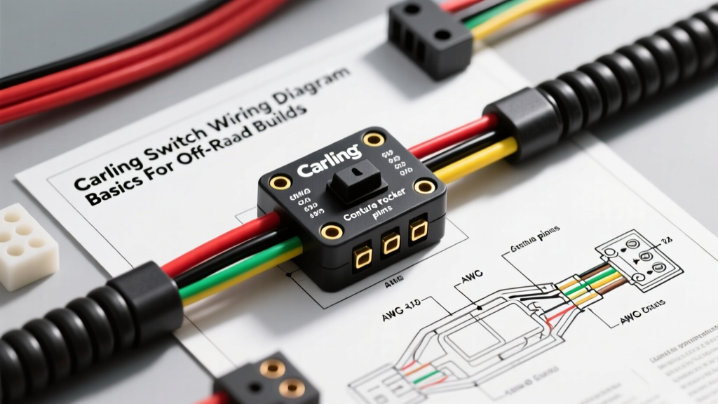
When upgrading the electrical system of a Jeep Wrangler, Ford Raptor, or custom UTV, the carling switch wiring diagram becomes your most critical reference. Carling Technologies, specifically their Contura V-Series, has become the gold standard for marine and off-road dash panels. These rocker switches offer IP68-sealed waterproof protection, making them ideal for exposed environments where mud, water, and dust would instantly destroy standard OEM toggle switches.
For beginners stepping into custom automotive wiring, the back of a Carling switch can look intimidating. With up to 10 individual spade terminals, understanding which pin controls the primary load, the independent dash illumination, and the dependent status LED is essential. This guide breaks down the fundamentals of Carling switch pinouts, proper AWG wire sizing according to SAE J1128 primary cable standards, and the critical necessity of relay integration for high-amp inductive loads.
Decoding the Carling Switch Wiring Diagram
The most common switch used in off-road light bar and accessory panels is the 10-Pin SPST (Single Pole, Single Throw) Contura V-Series with independent and dependent LEDs. This configuration allows the top LED to illuminate when your vehicle's headlights turn on (dash illumination), while the bottom LED illuminates only when you flip the switch to activate your accessory.
All terminals on these switches utilize standard 0.250-inch (1/4-inch) quick-disconnect spades. Expert Tip: Never use standard slip-joint pliers to crimp these connectors. You must use a dedicated ratcheting wire crimper to achieve a gas-tight crimp. A poor crimp introduces resistance, which generates heat and causes voltage drop, ultimately leading to melted switch housings or dim auxiliary lights.
Understanding the 10-Pin Configuration
To master the carling switch wiring diagram, you must divide the 10 pins into three distinct circuits: the primary switching circuit, the LED ground circuit, and the LED illumination circuit.
- Primary Circuit (Pins 2 & 3): This handles the actual 12V+ switching. Power enters the switch and exits to your load or relay.
- LED Ground Circuit (Pins 7 & 8): Carling switches use internal resistors for their LEDs. Pins 7 and 8 must be tied to a clean chassis ground to complete the LED circuit.
- Illumination Circuit (Pins 9 & 10): These provide 12V+ to the internal LEDs. Pin 9 is for the independent (top) LED, and Pin 10 is for the dependent (bottom) LED.
10-Pin Contura V-Series Pinout Specification Chart
Use the table below as your quick-reference guide when building your custom switch harness. Wire color suggestions follow standard automotive aftermarket conventions (similar to those found in Painless Performance wiring kits).
| Pin Number | Terminal Function | Recommended Wire Color | AWG Size (Relay Trigger) |
|---|---|---|---|
| 2 | 12V+ Power In (From fused ignition/battery source) | Red | 16 AWG |
| 3 | 12V+ Power Out (To Relay Coil Pin 86) | Blue | 16 AWG |
| 7 | LED Ground (To Chassis Ground) | Black | 18 AWG |
| 8 | LED Ground (Jumper to Pin 7) | Black (Jumper) | 18 AWG |
| 9 | Independent LED 12V+ (Dash Illumination Circuit) | Orange or White | 18 AWG |
| 10 | Dependent LED 12V+ (Jumper to Pin 2 for switched operation) | Red (Jumper) | 18 AWG |
Note: If you are using a 7-pin switch, it lacks the independent illumination pins (9 and 10). You will only wire pins 2, 3, 7, and 8.
Why You Must Use a Relay (The Inductive Load Problem)
A common beginner mistake when reading a carling switch wiring diagram is assuming the switch can handle the full amperage of the accessory. While the Contura V-Series is rated for 20 Amps at 12V DC, this rating applies strictly to resistive loads.
Most off-road accessories—such as LED light bars, winch solenoids, ARB air compressors, and cooling fans—are inductive loads. When an inductive circuit is broken (when you flip the switch off), the collapsing magnetic field creates a massive voltage spike known as inductive kickback. This spike causes micro-arcing inside the Carling switch, rapidly pitting the copper contacts, increasing resistance, and eventually melting the plastic housing. Always use the Carling switch to trigger a standard ISO mini relay (Bosch-style 30A/40A), allowing the heavy current to bypass the switch entirely.
Step-by-Step Relay Integration Guide
To safely wire your Carling switch to a high-amp accessory, follow this standard 4-pin relay integration sequence:
- Switch Power In (Pin 2): Run an 16 AWG red wire from a 12V+ ignition-switched fuse panel to Carling Pin 2.
- Dependent LED Jumper (Pin 10 to Pin 2): Install a small 18 AWG jumper wire between Pin 2 and Pin 10. This ensures the bottom LED lights up only when the switch receives power and is turned on.
- Switch Power Out (Pin 3): Run an 16 AWG blue wire from Carling Pin 3 to Relay Pin 86 (Coil Positive).
- LED Ground (Pins 7 & 8): Jumper Pin 8 to Pin 7, then run an 18 AWG black wire from Pin 7 to a clean, bare-metal chassis ground.
- Independent LED (Pin 9): Run an 18 AWG white wire from Carling Pin 9 to your vehicle's headlight illumination circuit (often found at the headlight switch or radio harness).
- Relay Load Wiring:
- Relay Pin 30: Run 10 AWG or 12 AWG wire directly from the positive battery terminal, passing through an appropriately sized inline fuse (e.g., 30A fuse for a 20A light bar).
- Relay Pin 87: Run 12 AWG wire from Pin 87 to the positive terminal of your accessory.
- Relay Pin 85: Run 16 AWG wire from Pin 85 to a clean chassis ground.
Real-World Troubleshooting & Common Mistakes
Even with a perfect carling switch wiring diagram on paper, physical installation can introduce faults. Use this diagnostic tree to solve common issues:
Symptom: The switch illuminates, but the accessory does not turn on.
- Cause A: You wired the load directly to Pin 3 without a relay, and the inline fuse blew due to inrush current.
- Cause B: Relay Pin 85 (Coil Ground) has a poor connection. The relay coil requires a complete circuit to energize the electromagnet.
- Fix: Verify ground continuity at Relay Pin 85 using a multimeter. Check the main power fuse at Relay Pin 30.
Symptom: The switch housing is hot to the touch.
- Cause: You are pulling high amperage (15A+) directly through the switch contacts, or your 1/4" spade crimps are loose, creating high electrical resistance.
- Fix: Immediately disconnect the battery. Inspect the spade terminals for looseness. If the switch is triggering a relay and still getting hot, check for a short circuit on the blue trigger wire between Pin 3 and Relay Pin 86.
Symptom: The independent LED (Top) does not light up with the headlights.
- Cause: Carling LEDs are polarity-sensitive. Alternatively, Pin 7/8 ground is missing. The internal LEDs share a common ground path; if the main ground is severed, neither LED will function correctly.
- Fix: Ensure Pins 7 and 8 are securely grounded. Verify that the 12V+ illumination source connected to Pin 9 is active when the headlight switch is engaged.
Pro-Tips for Longevity in Harsh Environments
When routing your wire harness through the firewall or under the hood, always use automotive-grade GXL or TXL wire, which features high-temperature, cross-linked insulation resistant to oil and abrasion. Finally, apply a small dab of dielectric grease to the 1/4" spade terminals before pushing them onto the Carling switch. This prevents galvanic corrosion and moisture ingress, ensuring your custom dash panel functions flawlessly for years on the trail.