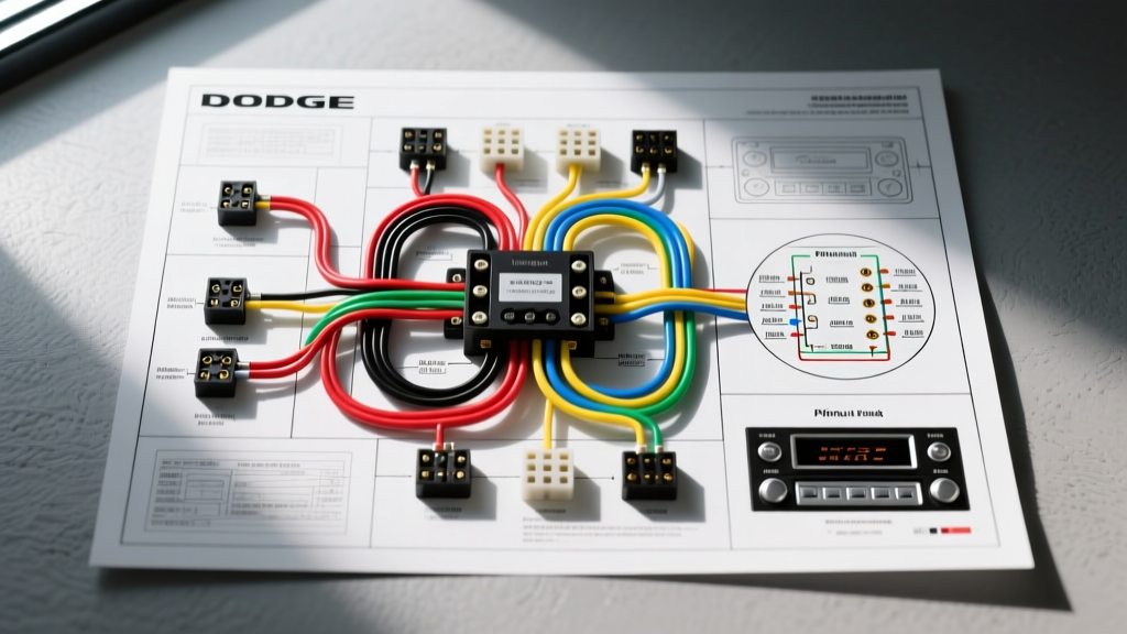
Introduction to the 1999 Dodge Ram Audio Architecture
The second-generation Dodge Ram (BR/BE platform) represents a transitional era in Chrysler automotive electrical systems. When consulting a 1999 dodge ram stereo wiring diagram, technicians and audio integrators will notice a distinct absence of complex multiplexed data buses for audio routing. Instead, the 1999 model year relies on a robust, hardwired analog architecture utilizing standard Chrysler mini-ISO style rectangular connectors. Whether you are diagnosing a parasitic battery draw, replacing a failed factory head unit, or integrating a modern digital signal processor (DSP), understanding the exact pinout, wire gauge, and circuit logic is critical.
Unlike modern vehicles that utilize CAN-bus or PCI-bus networks to wake up audio modules, the 1999 Ram uses discrete 12-volt triggers and direct analog speaker-level outputs. This makes aftermarket integration straightforward, provided you account for the factory Infinity amplified system variations and the notorious Ignition Off Draw (IOD) fuse circuit.
Main Radio Harness Pinout: C1 (Power & Accessory)
The primary power and accessory functions are routed through the C1 connector, a 7-pin black rectangular housing. According to SAE J1199 standards for automotive electrical connectors, these terminals are designed to handle continuous low-amperage loads. The factory power wires are typically 18 AWG, while illumination and trigger circuits step down to 20 AWG.
| Pin | Wire Color | Function | AWG | Diagnostic Notes |
|---|---|---|---|---|
| 1 | Pink/White | Constant 12V+ (Battery) | 18 | Fed via IOD Fuse. Hot at all times. |
| 2 | Red/White | Switched 12V+ (Ignition) | 18 | Hot in ACC and RUN positions. |
| 3 | Black/Light Green | Chassis Ground | 18 | Verify < 0.1V drop to battery negative. |
| 4 | Orange | Illumination / Dimmer | 20 | Variable voltage (0V-12V) via headlight switch. |
| 5 | Dark Green/Red | Amp Turn-On / Mute | 20 | 12V when radio is ON. Drops to 0V when OFF. |
| 6 | - | Empty | - | Reserved for optional CD changer data. |
| 7 | - | Empty | - | Not populated in base audio systems. |
Speaker Routing & Impedance Specifications: C2 Connector
The C2 connector (8-pin, gray housing) carries the analog audio signals to the four cabin speakers. In the base audio system, these wires run directly from the head unit's internal amplifier IC to the door and rear cab speakers. The factory wiring utilizes 20 AWG stranded copper, which is sufficient for the low-wattage (typically 7-10 watts RMS per channel) factory head unit but must be upgraded if running high-power aftermarket amplifiers.
| Speaker Location | Positive (+) Wire | Negative (-) Wire | Impedance |
|---|---|---|---|
| Left Front (Door) | Dark Green | Dark Green/Black | 4 Ohms |
| Right Front (Door) | Violet | Violet/Dark Green | 4 Ohms |
| Left Rear (Cab) | Brown/Red | Brown | 4 Ohms |
| Right Rear (Cab) | Dark Blue/Red | Dark Blue/White | 4 Ohms |
Reference: For comprehensive factory electrical schematics and grounding point locations, consult the Haynes Dodge Ram Pick-up Repair Manual, which details the specific chassis ground studs located behind the kick panels.
Advanced Deep Dive: The Infinity Gold Amplified System
If your 1999 Ram is equipped with the premium Infinity Gold audio package, the wiring topology changes significantly after the C2 connector. The head unit in an Infinity system does not drive the speakers directly. Instead, it outputs low-level (line-level) or heavily attenuated speaker-level signals that are routed to an external 4-channel amplifier.
Infinity Amplifier Location and Power
The factory Infinity amplifier is typically mounted behind the passenger-side kick panel or under the rear seat in Extended Cab models. It requires three critical inputs to function:
- Power (12V+): Fed directly from the PDC (Power Distribution Center) under the hood via a dedicated 20A fuse.
- Ground: Secured to a dedicated chassis stud. Corrosion here is a primary cause of alternating whine or complete system failure.
- Turn-On Trigger: The Dark Green/Red wire from Pin 5 of the C1 harness. If this wire is severed or the head unit is replaced without an aftermarket amp turn-on adapter, the factory amp will never wake up, resulting in a "radio turns on but no sound" scenario.
Bypassing the Factory Amp
When installing an aftermarket head unit in an Infinity-equipped Ram, you must either use a specialized wiring harness (such as the Metra 70-1817) that includes a built-in step-up transformer and amp trigger logic, or you must bypass the factory amplifier entirely. Bypassing involves running new 16 AWG or 14 AWG speaker wires directly from the new head unit to the door and rear cab speakers, completely abandoning the factory Infinity amp and its degraded 20-year-old capacitors.
Troubleshooting Matrix: Common 1999 Ram Audio Faults
Diagnosing electrical gremlins in the 2nd Gen Ram requires a systematic approach. Use the following decision tree to isolate common audio failures.
Symptom 1: Radio Display is Dead / No Power
- Check the IOD Fuse: Locate the interior Junction Block (JB) on the driver's side dash. Find the Ignition Off Draw (IOD) fuse (typically 10A). This fuse protects the constant 12V memory circuit (Pink/White wire). If blown, the radio will not power up.
- Verify Switched Power: Use a digital multimeter (DMM) to probe Pin 2 (Red/White) on the C1 harness with the key in the ACC position. You should read 12.2V - 12.6V.
- Test Ground Integrity: Measure resistance between Pin 3 (Black/Light Green) and a known good chassis ground. It should read less than 0.5 ohms. If higher, clean the ground ring terminal behind the dash.
Symptom 2: Radio Turns On, But No Audio Output
- Identify Audio System Type: Determine if the vehicle has the base system or the Infinity system. Look for the "Infinity" logo on the head unit or door speaker grilles.
- Test Amp Turn-On: If equipped with Infinity, probe the Dark Green/Red wire at the radio harness. It must show 12V when the radio is powered on. If it reads 0V, the aftermarket head unit's remote turn-on lead (usually blue/white) has not been properly spliced into this circuit.
- Check Speaker Shorts: The factory head unit's internal IC will shut down if it detects a short to ground. Disconnect the C2 harness and measure resistance between each speaker negative wire and chassis ground. An open line (OL) is expected; a reading near 0 ohms indicates a pinched wire in the door jamb boot.
Symptom 3: Radio Loses Memory (Presets/Clock) on Restart
This is almost exclusively caused by a loss of constant 12V power on Pin 1 (Pink/White). In the 1999 Ram, this circuit is tied to the IOD fuse. If the fuse is intact, check for voltage drop across the fuse contacts. Chrysler junction blocks from this era are prone to terminal spread, where the female spade connectors inside the fuse block lose tension, causing intermittent contact. Slightly bending the fuse prongs outward can temporarily restore tension, but replacing the JB terminal is the permanent fix.
Aftermarket Integration & AWG Upgrades
When upgrading the audio system in a 1999 Dodge Ram, relying on the factory 18 AWG power wires to feed a modern high-current head unit (which can draw up to 15A on peak transients) will result in voltage sag and headlight dimming synchronized to the bass. For head units with built-in 4x50W MOSFET amplifiers, or when installing a dedicated Line Output Converter (LOC) for a subwoofer amplifier, run a dedicated 12 AWG or 10 AWG constant 12V power wire directly from the battery or the PDC stud, protected by an inline 15A ATO fuse.
Always use a high-quality line driver or LOC with a built-in ground loop isolator if tapping into the factory speaker wires for an aftermarket subwoofer amp. The 1999 Ram's charging system, particularly the PCM-controlled alternator field circuit, is highly susceptible to introducing alternator whine into aftermarket audio grounds if the chassis ground points are not sanded down to bare metal and treated with dielectric grease.