The High Stakes of Security System Integration
Installing an aftermarket remote start and security system requires surgical precision. When technicians and DIY enthusiasts reference a Bulldog Security wiring diagram for systems like the 530T or 534T series, they are interfacing directly with the vehicle's most sensitive electronic control modules. A single misinterpreted pinout or undersized wire tap can result in catastrophic failures, ranging from fried Body Control Modules (BCMs) to unintended vehicle movement. According to the Mobile Electronics Certification Professional (MECP) guidelines, over 60% of remote starter failures and vehicle electrical gremlins stem from improper wire splicing, inadequate grounding, and a fundamental misunderstanding of ignition circuit topology. This guide dissects the most dangerous mistakes made when interpreting Bulldog Security schematics and outlines the strict safety protocols required for a reliable, hazard-free installation.
Critical Bulldog Wiring Diagram Misinterpretations
Mistake 1: Confusing Ignition 1, Ignition 2, and Accessory
The heavy-gauge 6-pin main power harness on Bulldog remote starters is the lifeline of the system. It typically includes Red (12V Constant), Black (Ground), Pink (Ignition 1), Orange (Ignition 2), Purple (Accessory), and Yellow (Starter). A pervasive mistake is treating all ignition outputs as interchangeable. In modern CAN-bus and multiplexed vehicles, Ignition 1 (often the main ECU wake-up circuit) must remain hot during the cranking cycle. Ignition 2, however, frequently drops to 0V during crank to shed non-essential loads and preserve battery voltage for the starter motor. If an installer swaps the Pink and Orange wires based on a generic assumption rather than testing the vehicle's OEM ignition switch with a digital multimeter (DMM), the ECU will lose power during cranking. The engine will never start, and the remote starter will time out, throwing a false 'crank failure' diagnostic code.
Mistake 2: Undersizing High-Current Pigtails
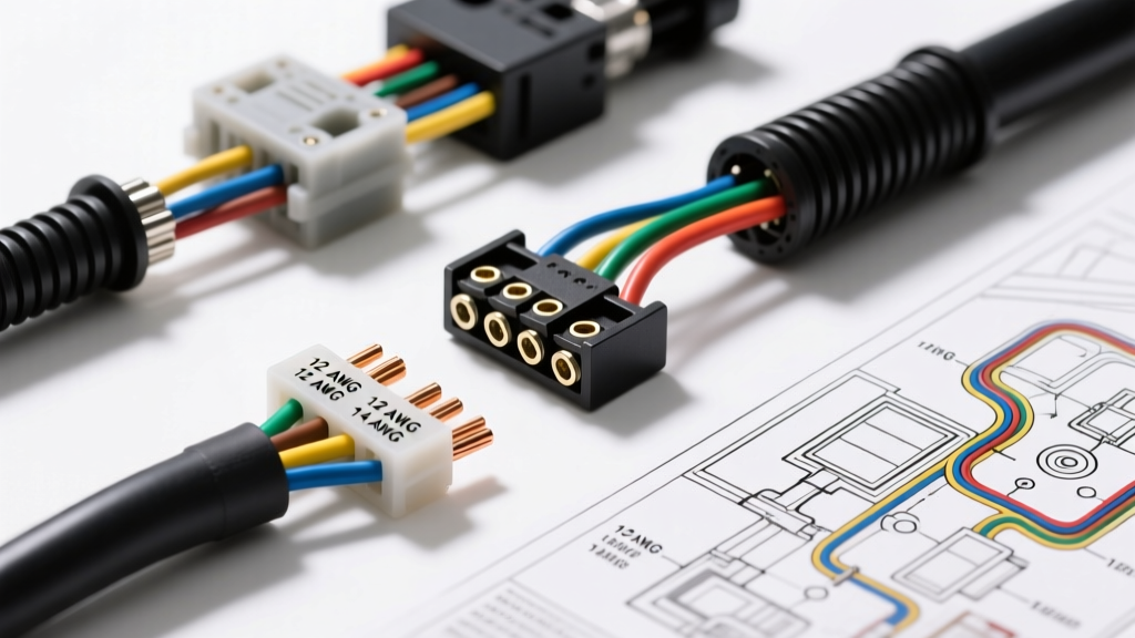
Bulldog Security harnesses are often terminated with 12 AWG or 14 AWG pigtails. However, the OEM ignition and starter circuits in V8 trucks and high-compression SUVs frequently utilize 10 AWG or even 8 AWG wiring to handle inductive loads exceeding 40 amps. Splicing a 14 AWG remote starter wire into a 10 AWG OEM harness creates a severe bottleneck. Under the SAE J1128 Low Tension Primary Cable standard, this gauge mismatch induces massive voltage drop and localized resistance. During a hot-soak restart in summer, the undersized wire acts as a resistor, generating enough heat to melt the insulation and potentially cause an under-dash electrical fire. Always verify the OEM wire gauge and step up the remote starter pigtail using high-strand-count, oxygen-free copper wire before making the final splice.
Mistake 3: Tapping the Wrong Tachometer Signal Source
The remote starter requires a tachometer signal to verify that the engine has successfully started, prompting it to disengage the starter relay. The Bulldog diagram usually designates a specific wire (often Green/White on the H3 connector) for the tach input. A critical mistake is tapping a digital CAN-bus data line or a smart-alternator LIN-bus wire, assuming it carries an analog RPM pulse. This results in a 'No Tach' error. The system will crank for the maximum programmed duration (usually 0.8 to 4.0 seconds), leading to horrific 'starter grind' as the Bendix gear clashes with the already-spinning flywheel ring gear. If the vehicle uses a digital tach signal, an interface module (like an iDatalink Maestro or Fortin EVO) is mandatory to translate the CAN data into an analog square-wave pulse the Bulldog brain can read.
The Neutral Safety Switch (NSS) Bypass Hazard
Perhaps the most life-threatening mistake in remote starter installation is improperly wiring the Neutral Safety Switch input. On Bulldog diagrams, this wire (often Brown or Black/White depending on the exact harness revision) must be wired to the vehicle's PRNDL switch so that it only sees a ground path when the transmission is in Park or Neutral. Never hardwire this input directly to chassis ground. If an installer bypasses the NSS to save time, the vehicle will remote-start in any gear. If the vehicle was left in Drive or Reverse, the moment the remote start sequence engages, the vehicle will lurch forward or backward, potentially running over the user or striking property. Always test the OEM NSS circuit with a DMM to ensure it transitions from Open Loop (OL) in Drive to less than 5 ohms of resistance in Park before connecting it to the Bulldog brain.
Safety Warnings: Circuits You Must NEVER Tap
Modern vehicles are rolling networks. Tapping into the wrong harness can trigger airbag deployments or brick the powertrain control module. Consult the table below before applying any T-tap or solder joint.
| Circuit Type | Common OEM Wire Colors | Hazard of Tapping | Required Alternative |
|---|---|---|---|
| SRS / Airbag | Yellow, Orange/Yellow | Accidental deployment, SRS module lockout | Strict avoidance; route harnesses away from SRS looms |
| CAN-Bus High/Low | Twisted pairs (Green/White, Orange/Black) | Network collision, U-Codes, BCM bricking | Use a CAN-bus interface module for data extraction |
| ABS / Stability Control | Red/Black, Shielded pairs | Wheel speed sensor skew, ABS fault codes | Do not tap; use OBD-II port for speed data if needed |
| Smart Alternator LIN | Single thin wire (often Gray or Violet) | Overcharging, battery boiling, PCM damage | Use dedicated analog tach adapters on injector coils |
For comprehensive safety data regarding supplemental restraint systems, always refer to the NHTSA Airbag Safety Guidelines before routing any aftermarket wiring harnesses behind the kick panels or steering column.
Door Lock Actuator Topology and BCM Frying
Bulldog Security systems provide various lock output harnesses to accommodate different vehicle architectures. A devastating mistake occurs when an installer misidentifies a 5-wire alternating 12V system (common in older GM vehicles) as a 3-wire negative pulse system (common in Ford and Chrysler). If you wire a standard negative-pulse relay harness to a 5-wire alternating system, the moment the doors attempt to lock, 12V is backfed directly into the BCM's low-side drivers. This instantly vaporizes the internal traces of the BCM, resulting in a $1,500+ replacement and dealership programming nightmare. Always use a DMM to test the lock/unlock wires. If they show 12V resting and drop to 0V upon actuation, it is a negative pulse. If they rest at 0V and spike to 12V in alternating polarities, you must use a Double-Pole Double-Throw (DPDT) relay setup or a specialized 5-wire lock harness.
Proper Splicing and Grounding Protocols
The 'Bulldog system resets when cranking' symptom is almost exclusively a grounding issue. The main ground wire (Black, 10 AWG) must be terminated to bare, unpainted chassis metal using a properly crimped 8mm or 10mm ring terminal. The ground run must be less than 18 inches. Grounding to a seatbelt bolt or a painted bracket introduces resistance. When the starter motor draws 200+ amps, the voltage potential across the poor ground spikes, causing the Bulldog brain's internal low-voltage reset circuit to trip, killing the cranking sequence mid-cycle.
Furthermore, abandon the use of scotch-locks and cheap T-taps. These pierce the wire insulation, exposing the copper strands to atmospheric moisture. Within six months, galvanic corrosion will wick under the insulation, causing high-resistance faults that are nearly impossible to diagnose. The only acceptable methods for splicing signal wires are the military splice (soldered and sealed with adhesive-lined dual-wall heat shrink) or high-quality crimp connectors that meet IPC/WHMA-A-620 standards. By respecting the engineering behind the Bulldog Security wiring diagram and adhering to these strict safety protocols, you ensure a remote start system that is both reliable and fundamentally safe.