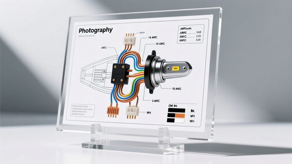
Introduction to Basic Headlight Circuit Architecture
Understanding a basic headlight wiring diagram is fundamental for any automotive electrical technician, restorer, or advanced DIY enthusiast. While modern vehicles utilize complex CAN-bus networks, LIN-bus subnets, and Body Control Modules (BCMs) to manage exterior lighting, the foundational architecture of a standard headlight circuit remains rooted in classical 12V DC relay-switch logic. This technical specification reference dissects the standard relay-driven headlight circuit, providing exact wire gauges, DIN 72552 relay pinouts, and SAE-compliant diagnostic parameters. By mastering these baseline specifications, you can accurately diagnose voltage drops, upgrade to high-draw LED or HID systems, and fabricate custom harnesses that meet strict automotive safety standards.
Core Component Specifications and Ratings
A standard, non-multiplexed headlight circuit consists of four primary nodes: the power source (battery/alternator), the control switch (dashboard or steering column), the switching mechanism (ISO mini relay), and the load (headlight bulb). In older or simpler vehicles, the headlight switch carries the full amperage load of the headlights. However, this generates excessive heat and leads to premature switch failure. The modernized basic headlight wiring diagram utilizes a low-amperage control circuit to trigger a high-amperage relay, ensuring the dashboard switch only handles the relay coil's minimal current draw.
ISO Mini Relay Specifications (DIN 72552)
The standard ISO 7588 mini relay is the industry benchmark for automotive lighting circuits. These relays are rated for harsh under-hood environments, featuring sealed epoxy or resin-filled cavities to prevent moisture ingress and contact corrosion. When reading a basic headlight wiring diagram, you will encounter the DIN 72552 terminal numbering standard. Understanding these terminal numbers is critical for proper pinout identification and multimeter testing.
| DIN Terminal | Function | Standard Wire Size (AWG) | Circuit Role |
|---|---|---|---|
| 30 | Common / Battery Power Input | 12 or 14 AWG | Constant 12V+ from battery via fusible link |
| 85 | Coil Ground | 16 or 18 AWG | Chassis ground or BCM-controlled ground path |
| 86 | Coil Power Input | 16 or 18 AWG | Switched 12V+ from headlight/dimmer switch |
| 87 | Normally Open (NO) Contact | 12 or 14 AWG | Output to headlight bulb positive terminal |
According to Mouser Electronics automotive relay specifications, a standard 12V DC relay coil typically exhibits a resistance of 60 to 80 ohms, drawing approximately 150mA to 200mA. This low current draw protects the delicate copper traces inside the steering column combination switch from thermal degradation.
H4/9003 Halogen Headlight Pinout and Load Specs
The H4 (European standard) or 9003 (US DOT equivalent) is the most common dual-filament headlight bulb used in basic headlight wiring diagrams. It features a three-prong connector that dictates the grounding and power delivery for both low and high beams. Unlike single-filament bulbs (e.g., H7 or H11) which require two dedicated relays per side, the H4 utilizes a shared ground path.
| Bulb Pin | Function | Typical Wattage | Current Draw (at 13.5V) |
|---|---|---|---|
| Pin 1 (Center/Offset) | Shared Ground (-) | N/A | Combined Return Path |
| Pin 2 | Low Beam Power (+) | 55W | ~4.1 Amps |
| Pin 3 | High Beam Power (+) | 60W | ~4.4 Amps |
Note: When upgrading to aftermarket LED or HID kits using an H4 base, the basic headlight wiring diagram must be modified to include a PWM (Pulse Width Modulation) bypass capacitor or a CAN-bus decoder if the vehicle's BCM monitors the circuit for bulb-out conditions based on current draw anomalies.
SAE J1128 Wire Gauge and Current Capacity Matrix
Selecting the correct wire gauge is critical to preventing voltage drop and thermal runaway. Automotive wire is manufactured to SAE J1128 standards, which dictate the strand count, insulation thickness, and temperature ratings (typically 105°C to 125°C for cross-linked polyethylene insulation). Unlike household AWG wire, automotive SAE wire has a thinner copper cross-section for a given gauge number, meaning you must size your wiring based on automotive-specific ampacity charts.
| Circuit Segment | Max Continuous Load | Minimum SAE Wire Gauge | Max Recommended Length (One Way) |
|---|---|---|---|
| Battery to Main Relay (Terminal 30) | 20 Amps | 12 AWG | 10 Feet |
| Relay to Headlight Bulb (Terminal 87) | 10 Amps | 14 AWG | 8 Feet |
| Switch to Relay Coil (Terminal 86) | 2 Amps | 18 AWG | 12 Feet |
| Headlight Ground Return Path | 10 Amps | 14 AWG | 4 Feet |
Standardized OEM Wire Color Coding
While there is no universal, legally mandated color code for 12V automotive lighting across all global manufacturers, the industry generally adheres to a standardized palette derived from DIN and SAE recommendations. When tracing a basic headlight wiring diagram on a workbench or in a vehicle, expect the following color conventions:
- Red or Red/White Stripe: Constant battery power (Terminal 30 feeds).
- Black or Black/White Stripe: Primary chassis ground paths.
- Yellow or Yellow/Black Stripe: Switched power from the headlight switch to the relay coil.
- Green or Green/White Stripe: High beam indicator and high beam relay trigger feeds.
- Blue or Blue/Red Stripe: Low beam power delivery to the bulb.
Always verify wire functions with a digital multimeter (DMM), as previous owners or aftermarket stereo installers frequently violate OEM color codes when splicing into lighting circuits.
Diagnostic Troubleshooting and Voltage Drop Testing
The most common failure mode in a basic headlight wiring diagram is not a blown fuse, but excessive resistance caused by corroded connectors, undersized wiring, or degraded relay contacts. According to Bosch Automotive Electrics and Electronics guidelines, a healthy 12V lighting circuit should deliver a minimum of 12.0V to the bulb under load to ensure optimal lumen output and prevent premature filament failure.
Voltage Drop Testing Protocol
To accurately diagnose resistance issues, perform a voltage drop test with the circuit energized (headlights turned ON). Set your DMM to DC Volts.
- Power Side Test: Place the red probe on the battery positive post and the black probe on the headlight bulb's positive terminal. A reading greater than 0.20V indicates excessive resistance in the power feed (check relay contacts, fusible links, and bulkhead connectors).
- Ground Side Test: Place the red probe on the headlight bulb's ground terminal and the black probe on the battery negative post. A reading greater than 0.10V indicates a poor chassis ground. Clean the grounding ring terminal, remove paint/rust from the chassis mating surface, and apply dielectric grease.
- Relay Coil Test: If the relay fails to click, measure resistance across terminals 85 and 86. An open loop (OL) indicates a burnt internal coil winding requiring relay replacement.
Summary of Best Practices
When designing, repairing, or modifying a basic headlight wiring diagram, always prioritize heavy-gauge power feeds, sealed automotive-grade connectors (such as Deutsch DT or Weather-Pack series), and proper inline fusing located within 18 inches of the battery source. By adhering to SAE wire sizing, DIN relay pinouts, and strict voltage drop thresholds, you ensure maximum lumen output, circuit longevity, and compliance with automotive fire safety standards.