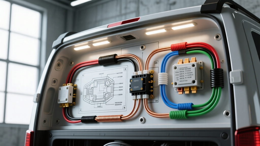
The 12V DC Reality: Why Residential Diagrams Fail in Vehicles
Customizing the interior of a Ford Transit, Mercedes Sprinter, or a truck camper shell often requires integrating low-profile illumination. When searching for a wiring diagram for recessed lights, most search results cater to 120V AC residential grids. However, automotive 12V DC systems require an entirely different approach, focusing on voltage drop, vibration-resistant terminations, and relay-driven load management. Recessed LED puck lights in a van build or truck topper are typically rated between 3W and 5W each. While this seems like a negligible load, running long wire harnesses through a high-roof Sprinter or a 24-foot truck camper introduces significant resistance, making proper wire gauge selection and relay integration mandatory for a safe, fire-free installation.
Calculating Load and Selecting AWG Wire
Unlike household wiring, automotive electrical systems operate on a nominal 12.6V (resting battery) to 14.4V (alternator charging) spectrum. To determine the correct American Wire Gauge (AWG) for your recessed lighting array, you must calculate the total amperage draw and factor in the length of the wire run to prevent voltage drop. A voltage drop exceeding 3% will result in dimming at the furthest recessed light in the daisy chain.
According to the SAE J1128 Low Tension Primary Cable standards, automotive wire is stranded and rated for specific temperature thresholds. You must use stranded copper wire (never solid core residential Romex, which will snap under vehicle vibration).
| Total Lights (4W each) | Total Wattage | Amperage @ 14.4V | Main Feed AWG | Branch Drop AWG | Inline Fuse Size |
|---|---|---|---|---|---|
| 4 Pucks | 16W | 1.11A | 16 AWG | 18 AWG | 5A Mini-ATM |
| 8 Pucks | 32W | 2.22A | 14 AWG | 18 AWG | 10A ATC |
| 12 Pucks | 48W | 3.33A | 12 AWG | 16 AWG | 10A ATC |
| 16 Pucks | 64W | 4.44A | 12 AWG | 16 AWG | 15A ATC |
The Core Wiring Diagram for Recessed Lights (Relay Circuit)
A common mistake in van builds is wiring recessed lights directly to an OEM upfitter switch or an aftermarket toggle switch. While the switch may be rated for 20A, the long wire runs and potential inrush currents from LED drivers can overheat the switch contacts. The correct automotive wiring diagram for recessed lights utilizes a Bosch-style ISO mini relay to isolate the low-current trigger circuit from the high-current load circuit.
Standard 4-Pin Automotive Relay Pinout
The relay acts as a heavy-duty, electrically operated switch. The wiring diagram flows as follows:
| Pin Number | Function | Wire Color Code | Connection Destination |
|---|---|---|---|
| 30 | Common (Power In) | Red (12 AWG) | Direct to Battery Positive (via ATC Fuse) |
| 87 | Normally Open (Load Out) | Red (12 AWG) | Positive feed to recessed light array |
| 86 | Coil Trigger (Switch In) | Blue (18 AWG) | From OEM Upfitter Switch or Toggle Switch |
| 85 | Coil Ground | Black (18 AWG) | Chassis Ground or Battery Negative |
Step-by-Step Installation & Routing Guide
Step 1: Sourcing the Trigger and Main Power
For modern vehicles like the Ford Transit or F-Series Super Duty, consult the Ford Motor Company Body Builder Layout Book to locate the auxiliary upfitter switches. These switches provide a pre-fused 12V trigger signal. Run an 18 AWG blue trigger wire from the upfitter switch output to Pin 86 on your relay. Mount the relay in a protected, dry cavity, such as behind the B-pillar trim or inside a dedicated DC fuse block enclosure.
Step 2: Main Feed and Fuse Placement
Run a 12 AWG red primary wire from the positive battery terminal to Pin 30 on the relay. Critical Safety Rule: The inline ATC fuse holder must be installed within 18 inches of the battery positive terminal. If the wire chafes against the chassis anywhere along the run, this fuse will blow before the wire harness can catch fire. Use adhesive-lined heat shrink on all ring terminals connecting to the battery.
Step 3: Load Distribution and Branching
From Pin 87, run the main 12 AWG load wire to the ceiling cavity where the recessed lights are mounted. Because recessed LED puck lights typically feature short 18 AWG pigtails, you must create a distribution node. Instead of twisting wires and using electrical tape (which unravels in high-heat vehicle ceilings), use Wago 221 lever nuts housed inside a sealed plastic junction box, or utilize TE Connectivity automotive connectors for a fully waterproof, vibration-proof Deutsch DT style connection.
Step 4: Establishing the Ground Network
Do not rely on the sheet metal of a unibody van or the aluminum skin of a truck topper for a ground return without proper preparation. Paint, clear coat, and rust-proofing act as insulators. Scrape away the coating to bare metal, secure the 12 AWG black ground wire using a stainless steel ring terminal and a self-tapping screw or rivnut, and coat the terminal in dielectric grease to prevent galvanic corrosion. Connect all negative pigtails from the recessed lights to this centralized ground bus bar.
Crimp vs. Solder in High-Vibration Automotive Environments
A pervasive myth in the automotive DIY community is that soldering wires is superior to crimping. In a static residential environment, soldering recessed lights is standard. In a vehicle, soldering creates a rigid joint that will inevitably suffer from metal fatigue and snap due to chassis flex, road vibration, and thermal expansion. SAE standards dictate that open-barrel or closed-barrel crimps using a ratcheting crimper (such as the TE Connectivity CERTI-CRIMP series) create a cold-weld gas-tight connection that remains flexible and resilient over thousands of miles of travel. Always terminate your recessed light branch wires with proper crimped ferrules or butt connectors sealed with dual-wall adhesive heat shrink.
Troubleshooting Common 12V Recessed Light Failures
Flickering Lights and PWM Dimmer Incompatibility
If your recessed lights flicker rapidly when the vehicle is running, you may be dealing with a Pulse Width Modulation (PWM) signal. Many modern European vans (like the Mercedes Sprinter) use PWM to dim interior lighting or monitor bulb-out conditions via the CAN-bus system. Standard LED drivers in aftermarket recessed puck lights cannot interpret rapid PWM switching, resulting in a strobe effect. The Fix: Install a 12V DC LED anti-flicker decoder module (essentially a capacitor bank) between the relay load output and the light array to smooth the voltage ripple.
Severe Voltage Drop (Dimming at the End of the Run)
If the recessed lights near the power source are bright, but the lights at the far end of the truck camper are dim, you are experiencing voltage drop. The daisy-chain method of wiring pushes all the amperage through the first light's thin 18 AWG pigtail, creating a bottleneck. The Fix: Abandon the daisy-chain. Run a dedicated 14 AWG positive and negative 'home run' trunk line down the center of the ceiling, and use T-taps or Wago connectors to drop down to each individual recessed light, ensuring equal voltage delivery across the entire array.
Parasitic Draw Issues
If the recessed lights remain faintly illuminated (ghosting) even when the trigger switch is off, your relay may be wired backward, or you have induced voltage from running the trigger wire parallel to high-current AC inverter cables. Ensure Pin 86 receives the switched 12V and Pin 85 goes to ground. Reversing these on a standard relay works, but if your relay has an internal suppression diode, reversing the polarity will cause a dead short and blow the upfitter fuse immediately upon activation.