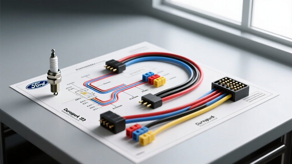
Understanding the Ford 302 Ignition and Spark Plug Wiring
When enthusiasts and mechanics search for a spark plug wiring diagram Ford 302 configurations, they are often looking for two distinct but interconnected systems: the high-tension spark plug wire routing and the low-tension ignition control harness. The Ford 302 cubic-inch (5.0L) Windsor V8 is one of the most iconic engines in automotive history, transitioning from breaker-point distributors to the legendary Duraspark II electronic ignition, and eventually to multi-port fuel injection (EFI) with Mass Air systems.
Selecting the correct ignition wiring harness requires a deep understanding of your engine's current setup. Whether you are restoring a classic 1970s Mustang with a factory Motorcraft Duraspark II module, upgrading to an MSD 6AL for high-RPM racing, or converting to a Holley Sniper EFI system, the wiring architecture changes dramatically. This guide compares the top ignition harness solutions for the Ford 302, provides exact pinout schematics, and details the critical high-tension spark plug wire routing required to prevent cross-firing and electromagnetic interference (EMI).
High-Tension Spark Plug Wire Routing & Firing Order
Before diving into the low-voltage control harnesses, it is critical to address the physical spark plug wire routing. The Ford 302 utilizes a specific firing order that, if wired incorrectly or routed poorly, will result in severe cross-firing, induction misfires, and erratic idle.
- Standard Ford 302 Firing Order: 1-3-7-2-6-5-4-8
- Passenger Side Cylinders (Front to Rear): 1, 2, 3, 4
- Driver Side Cylinders (Front to Rear): 5, 6, 7, 8
Cross-Firing Prevention: The most common wiring mistake on the 302 occurs between cylinders 5 and 6, as well as 1 and 3. Because these cylinders fire consecutively in the sequence and are physically adjacent on the engine block, running their spark plug wires parallel to one another induces a secondary voltage spike through capacitance. Always use wire looms and separators to ensure that consecutive firing wires cross at a 90-degree angle rather than running side-by-side. For high-output 302 builds, we recommend upgrading from the factory 7mm carbon-core wires to 8.5mm silicone-jacketed spiral-core wires (such as Motorcraft WR-4000 or Taylor StreetThunder) to suppress RFI while maintaining low resistance.
Product Comparison: OEM vs. Aftermarket Ignition Harnesses
Choosing the right low-tension wiring harness dictates how the ECU or ignition module signals the coil to fire the spark plugs. Below is a comparison of the three most common ignition wiring architectures for the Ford 302.
1. OEM Motorcraft Duraspark II Harness (Restoration & Daily Drivers)
The Duraspark II system, introduced in the late 1970s, relies on a magnetic pickup inside the distributor and an external ignition control module (typically mounted on the driver-side fender apron). The factory harness uses bulkhead connectors that pass through the firewall. While excellent for stock restorations, the factory 18 AWG pickup wires are highly susceptible to EMI from modern high-output alternators or aftermarket fuel pumps. If retaining the Duraspark II, we recommend rebuilding the harness using SAE J1128 compliant 16 AWG primary wire for the 12V feeds and shielded 20 AWG cable for the magnetic pickup signals.
2. MSD 6AL Universal Ignition Wiring Kit (High-Performance & Racing)
For 302 engines pushing past 6,000 RPM, the factory Duraspark module cannot sustain adequate dwell time or spark energy. The MSD 6AL (Part #6425) capacitive discharge system bypasses the factory module entirely. The MSD harness requires running heavy-duty 12 AWG red and black wires directly to the battery (or a dedicated 30A relay) to handle the massive current draw of the multiple-spark sequence. The factory Ford distributor magnetic pickup (Violet/Orange wires) plugs directly into the MSD's flying lead harness via a Weather-Pack connector, eliminating the need for the factory fender-mounted module.
3. Holley Sniper EFI / HyperSpark Conversion Harness (EFI Swaps)
When converting a carbureted 302 to EFI, the ignition wiring must integrate with the ECU for timing control. The Holley HyperSpark harness replaces the factory Duraspark module and provides a 5V reference signal and shielded magnetic pickup wiring directly to the Sniper ECU. This harness utilizes premium 18 AWG shielded twisted-pair wiring for the distributor pickup, which is absolutely mandatory to prevent the high-voltage spark plug wires from inducing 'noise' into the ECU's timing signal, which would otherwise cause erratic spark advance.
Ford 302 Spark Plug Wiring Diagram & Pinout Reference
Below is the definitive pinout and wire color reference for the most common Ford 302 ignition setup: the Duraspark II control module. Understanding this schematic is vital for troubleshooting or adapting the factory harness to an aftermarket relay board.
| Module Connector | Pin Position | Wire Color | AWG Size | Function / Destination |
|---|---|---|---|---|
| 4-Pin Connector | 1 | Red | 14 AWG | 12V+ from Ignition Switch (Run Position) |
| 4-Pin Connector | 2 | White | 16 AWG | 12V+ from Starter Solenoid 'I' Terminal (Start Bypass) |
| 4-Pin Connector | 3 | Violet | 18-20 AWG | Distributor Magnetic Pickup (+) Signal |
| 4-Pin Connector | 4 | Orange | 18-20 AWG | Distributor Magnetic Pickup (-) Signal |
| 2-Pin Connector | 1 | Green | 16 AWG | Coil Negative (-) Terminal & Tachometer Output |
| 2-Pin Connector | 2 | Black | 14 AWG | Chassis Ground (Must be grounded to unpainted metal) |
Note: The White wire (Start Bypass) is a critical component of the Ford 302 wiring diagram. During cranking, the ignition switch drops voltage to the Red wire to save amperage for the starter motor. The White wire pulls full battery voltage from the starter solenoid's 'I' terminal to ensure a hot spark while the engine is turning over.
Troubleshooting Common 302 Ignition Wiring Failures
Even with a perfect spark plug wiring diagram Ford 302 schematic in hand, real-world variables often cause electrical gremlins. Here is a diagnostic decision tree for common 302 ignition failures:
- Symptom: Engine has spark when the key is in the 'Run' position, but dies instantly when cranking.
Cause: The White 'Start Bypass' wire is disconnected or the starter solenoid 'I' terminal is corroded. The module is starving for voltage during crank. - Symptom: High-RPM misfire or backfire through the carburetor.
Cause: EMI interference on the Violet/Orange pickup wires. If these wires are routed near the alternator output or spark plug wires without shielding, the Duraspark module will read false triggers. Reroute using shielded twisted-pair cable. - Symptom: Coil burns out repeatedly.
Cause: Incorrect ballast resistor wiring. The Duraspark II system requires a specific 1.35-ohm ballast resistor wire integrated into the factory harness (often a pinkish cloth-covered wire). If bypassed with standard 12 AWG copper wire, the coil receives 14+ volts continuously and will overheat.
Expert Installation Tips & Torque Specifications
Proper physical installation is just as important as the electrical routing. When installing spark plug wires and ignition components on the Ford 302, adhere to these specifications:
- Spark Plug Torque: 15-20 lb-ft for aluminum cylinder heads; 22-28 lb-ft for cast iron heads. Always use a drop of anti-seize on the plug threads for aluminum heads to prevent galling.
- Spark Plug Gap: 0.044" for standard Duraspark II systems; 0.045"-0.050" for MSD capacitive discharge systems.
- Distributor Hold-Down Torque: 15 lb-ft. Over-tightening the distributor clamp can distort the 302's aluminum timing cover or restrict oil flow to the distributor shaft.
- Dielectric Grease: Apply a small amount of silicone dielectric grease inside the spark plug wire boots to prevent them from bonding to the ceramic insulator, which frequently causes the wire to tear upon removal during future maintenance.
For comprehensive vehicle-specific tear-downs and factory wiring schematics, mechanics frequently consult the Haynes Ford Full-Size Repair Manuals. Additionally, when adapting aftermarket capacitive discharge systems, referencing the MSD Performance Tech Support documentation ensures your heavy-gauge power wires are fused correctly at the battery to prevent catastrophic electrical fires.