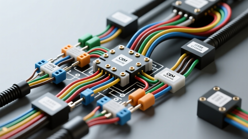
The Architecture of an ALLDATA Car Wiring Diagram
Professional automotive technicians rely on the ALLDATA car wiring diagram to navigate the labyrinth of modern vehicle electrical architecture. However, treating these schematics as simple point-to-point maps rather than complex logical flowcharts is a primary cause of misdiagnosed parasitic draws, phantom CAN-bus faults, and unnecessary module replacements. An advanced technical deep dive into ALLDATA's schematic presentation reveals that mastering the platform requires understanding how OEM data is aggregated, normalized, and indexed for diagnostic efficiency.
Unlike generic aftermarket manuals, ALLDATA pulls directly from OEM service information (such as GM Service Information, Ford PTS, and Toyota TIS). Yet, the way a technician interprets the 'Cavity' versus 'Pin' designations, splice pack nomenclature, and metric-to-AWG wire gauge conversions dictates the speed and accuracy of the repair. This guide dissects the advanced utilization of ALLDATA schematics for complex powertrain and network diagnostics.
Connector End-Views vs. Schematic Flow Logic
A common pitfall when using an ALLDATA car wiring diagram is confusing the schematic flow with the physical connector end-view. The schematic represents logical circuit flow—power sources on top, grounds on the bottom, and signal paths in between. It does not represent physical pin adjacency. For example, Pin 2 and Pin 72 on an ECM connector might be logically grouped on a schematic for a 5V reference circuit, but physically located on opposite sides of a 160-cavity connector. Technicians must cross-reference the 'Connector End View' tab in ALLDATA to map the schematic pin number to the physical cavity position before back-probing, preventing terminal splaying and connector damage.
Case Study: Tracing a 5V Reference Failure on GM Gen V Ecotec3
To demonstrate advanced schematic tracing, let us analyze a common failure mode on a GM 5.3L L83 (Gen V Ecotec3) engine: a corrupted 5-Volt Reference circuit causing simultaneous Throttle Position Sensor (TPS) and Manifold Absolute Pressure (MAP) sensor codes (e.g., P0121, P0222, P0107).
When pulling the ALLDATA car wiring diagram for the Engine Controls module, the 5V Reference circuit originates from the ECM. Let us break down the specific technical parameters provided by the OEM schematic:
- Module Connector: ECM X1 (Black Connector)
- Pin Cavity: Pin 28
- Wire Color: Pink with White Stripe (PK/WH)
- Wire Gauge: 0.50 mm² (Equivalent to 20 AWG)
- Splice Pack: SP205 (Splice Pack 205)
The schematic reveals that Pin 28 does not run directly to a single sensor. Instead, it routes to SP205, an internal harness splice pack that distributes the 5V reference to the TPS, MAP, and Accelerator Pedal Position (APP) sensors. If a technician simply tests voltage at the TPS and finds 4.2V, the schematic dictates that the fault could be the TPS pulling the circuit down, the MAP sensor pulling it down, or corrosion at SP205 itself.
By utilizing the ALLDATA diagram to locate the physical position of SP205 (typically wrapped in convoluted tubing near the engine harness breakout), the technician can isolate the splice. Cutting the PK/WH wire just after SP205 and testing the ECM side isolates the module. If the ECM side reads a clean 5.0V under load, the fault lies downstream in the harness or a specific sensor, validating the diagnostic tree without throwing parts at the vehicle.
ALLDATA Circuit Identifier & Splice Pack Reference
Understanding the standardized nomenclature within an ALLDATA car wiring diagram is critical for rapid circuit isolation. Below is a reference table for common OEM identifiers translated through the ALLDATA interface.
| Identifier Code | Schematic Meaning | Advanced Diagnostic Strategy |
|---|---|---|
| Sxxx / SPxxx | Splice / Splice Pack (e.g., SP205) | Common failure points for capillary action corrosion. Always verify voltage on both sides of the splice under loaded conditions. |
| Gxxx | Ground Point (e.g., G104) | Perform a voltage drop test from the sensor ground pin to the battery negative terminal. Do not rely on ohmmeter continuity tests. |
| Cxxx | Inline Connector (e.g., C105 Bulkhead) | Check for terminal fretting and moisture ingress. Use a drag-test tool on female terminals before applying dielectric grease. |
| Zxxx | Shield Drain / Noise Ground | Crucial for CAN-bus and high-speed data lines. Must have less than 0.1V drop to the chassis ground under network load. |
Advanced Diagnostic Strategy: Segmented Voltage Drop Testing
The most critical insight gained from an advanced reading of an ALLDATA car wiring diagram is the abandonment of continuity testing for voltage drop testing. Continuity testing uses less than 10 milliamps of current, which can easily pass through a single strand of 20 AWG copper. However, an ECU injector driver circuit requires 2 to 4 amps to actuate a solenoid. A single strand of copper will pass a continuity test but will instantly fail under load, resulting in a voltage drop and a misfire code.
Using the ALLDATA schematic, identify every intermediate connector (e.g., C105, C210) between the power source and the load. With the circuit energized and loaded, use your digital multimeter to measure the voltage drop across each segment of the wire and each connector cavity. According to SAE International standards for automobile electricity and electronics, a standard connection should exhibit no more than a 0.10V drop across a connector, and no more than 0.20V drop across a standard length of 18 AWG to 14 AWG wire under normal operating load. The schematic provides the exact routing to isolate these segments methodically.
Navigating CAN-Bus Schematics and Terminating Resistors
Modern network diagnostics require a profound understanding of how ALLDATA represents Controller Area Network (CAN) topologies. On an ALLDATA car wiring diagram, twisted pair data lines are often denoted by a specific twisted wire symbol or a textual note reading 'Twisted Pair'. For GM High-Speed GMLAN, the typical color coding is Dark Green (CAN High) and Dark Blue (CAN Low), usually 0.50 mm² (20 AWG).
The schematic will also indicate the location of the 120-ohm terminating resistors. These resistors are typically integrated into the physical modules at the extreme ends of the CAN-bus topology (e.g., the ECM and the BCM). When diagnosing a U0100 (Lost Communication with ECM) code, the ALLDATA diagram allows you to identify the exact pins at the Data Link Connector (DLC) or the ECM breakout to measure the parallel resistance. Two 120-ohm resistors in parallel must yield exactly 60 ohms. If the schematic shows a third module with an internal resistor (common in some European architectures), the expected parallel resistance will drop closer to 40 ohms. Misinterpreting the schematic's resistor placement leads to false diagnoses of 'shorted networks'.
Capacitive Coupling and Harness Routing
Advanced technicians use the ALLDATA wiring diagram not just for electrical continuity, but for physical harness routing context. High-voltage ignition secondary circuits or alternating current (AC) compressor clutch wires routed parallel to low-voltage sensor signal wires (like the 0.50 mm² MAF signal) can induce capacitive coupling. The schematic helps identify if a 5V reference wire shares the same harness cavity or conduit as a high-amperage injector feed, explaining intermittent signal noise that a standard oscilloscope might only catch under specific RPM loads.
Limitations and OEM Cross-Referencing
While the ALLDATA car wiring diagram is the industry standard for independent and collision repair facilities, it is not infallible. Occasional OCR (Optical Character Recognition) errors during the ingestion of OEM PDF schematics can result in swapped pin numbers or mislabeled wire colors. When a physical wire color blatantly contradicts the ALLDATA schematic, technicians must cross-reference with established diagnostic communities and OEM bulletins. Resources like the International Automotive Technicians Network (iATN) are invaluable for identifying known OEM schematic errata and discovering undocumented technical service bulletins (TSBs) regarding harness chafing points that the schematic cannot visually represent.
Mastering the ALLDATA car wiring diagram requires shifting from a passive reader of lines to an active analyst of electrical architecture. By leveraging connector end-views, understanding splice pack nomenclature, executing segmented voltage drop tests, and accurately interpreting CAN-bus topology, technicians can elevate their diagnostic accuracy and eliminate the guesswork from modern vehicle electrical repair.