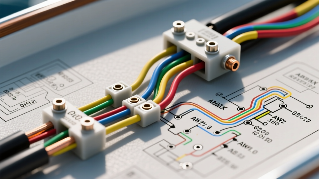
Introduction to Marine DC Architecture
Developing a comprehensive wiring diagram for boat applications requires a fundamental shift in thinking from standard automotive electrical design. While a car operates in a relatively dry, temperature-controlled environment, a marine vessel is subjected to salt spray, constant vibration, UV degradation, and extreme humidity. Consequently, marine DC systems must adhere to strict guidelines established by the American Boat and Yacht Council (ABYC), specifically the ABYC E-11 standard for AC and DC electrical systems. This advanced technical deep dive explores the schematic topology, conductor sizing, and failure-mode mitigation required to build or troubleshoot a robust 12V/24V marine DC network.
Why Automotive SAE Standards Fail on the Water
Automotive wire, typically built to SAE J1128 specifications, utilizes bare copper and standard PVC insulation. When exposed to marine environments, capillary action draws moisture down the wire strands, leading to internal 'black wire' corrosion that increases resistance and causes catastrophic voltage drop. A proper marine wiring diagram for boat systems mandates the use of UL 1426 Boat Cable. This cable features tinned copper conductors (which resist galvanic oxidation) and premium PVC or cross-linked polyethylene (XLPE) insulation rated for 105°C in dry locations and 60°C in wet locations. Furthermore, marine wire utilizes Type 3 fine stranding, offering superior flexibility to withstand the high-frequency vibrations of marine diesel and outboard engines without suffering from strand fatigue and breakage.
ABYC E-11 Compliant Color Code Matrix
One of the most critical distinctions when reading a wiring diagram for boat systems versus automotive systems is the color code. In automotive applications, black is universally ground. In marine DC systems, black is often used for the positive DC hot source. Misinterpreting these colors during troubleshooting can lead to dead shorts or destroyed electronics. Below is the standardized ABYC color matrix for DC wiring.
| Wire Color | Primary Application | Technical Notes & Constraints |
|---|---|---|
| Black or Red | DC Positive / Hot | Used for main battery feeds and primary positive distribution. |
| Yellow | DC Ground / Negative | Strictly reserved for DC negative return paths. Never use for AC. |
| Dark Blue | Fuses to Switches | Connects the DC fuse panel to the distribution switches. |
| Light Blue | Oil Pressure Sender | Instrumentation specific; connects gauge to engine sender. |
| Brown | Bilge Blower / Auxiliary | Used for ventilation blowers and general lighting circuits. |
| Green | DC Bonding Ground | Connects metal masses to the main DC negative bus for lightning/corrosion protection. |
Core Wiring Diagram for Boat DC Distribution
A professional-grade marine DC schematic is divided into three primary nodes: the main isolation bank, the uninterruptible safety circuits, and the switched distribution panel. Below is the node-by-node breakdown of the architecture.
Node 1: Main Battery Bank and Isolation
The heart of the system begins at the house and engine start battery banks. Unlike automotive systems that rely on a single battery, marine vessels utilize heavy-duty battery isolation switches (e.g., Blue Sea Systems m-Series). The positive terminals of the battery banks are routed via 2/0 AWG or 4/0 AWG tinned battery cable to a common positive bus bar. An Automatic Charging Relay (ACR) or Voltage Sensitive Relay (VSR) is wired between the house and start banks. The VSR monitors voltage; when the alternator pushes the system above 13.6V, the VSR's internal coil energizes, closing the heavy-duty contacts and combining the banks for charging. When voltage drops below 12.8V, it isolates the start battery to ensure cranking power is preserved. The negative returns are routed to a dedicated negative shunt, which feeds a battery monitor (e.g., Victron SmartShunt) before terminating at the main negative bus bar.
Node 2: The Uninterruptible Bilge Pump Circuit
The most critical circuit on any vessel is the bilge pump. According to ABYC standards, this circuit must remain energized even when the main battery disconnect switch is in the 'OFF' position. In our wiring diagram for boat safety systems, the bilge pump positive feed originates directly from the positive battery terminal or the unswitched side of the main bus. Crucial Specification: An inline ATC or MAXI fuse must be installed within 7 inches of the positive connection point. The wire (minimum 14 AWG, preferably 12 AWG for long runs to mitigate voltage drop) routes to a Single Pole Single Throw (SPST) float switch. The float switch must be rated for a minimum of 15A DC to handle the inductive startup spike of the bilge pump motor. From the float switch, the dark blue wire routes to the bilge pump positive terminal. The yellow ground wire returns directly to the negative bus bar.
Node 3: Navigation and Anchor Lighting
Navigation lights are governed by COLREGs and require strict voltage regulation. A wiring diagram for boat navigation circuits must account for a maximum allowable voltage drop of 3% (compared to the standard 10% for general DC accessories). If a 12V LED or incandescent masthead light experiences a voltage drop below 11.64V, it may fail to meet the required luminous range. To achieve this, conductors must be oversized. For a 40-foot run to the masthead light drawing 1.5A, a standard 16 AWG wire will result in a 4.5% drop. The schematic must specify 12 AWG wire to keep the drop well under the 3% threshold. All navigation circuits are routed through dedicated, illuminated circuit breakers on the main helm distribution panel.
Conductor Sizing and Voltage Drop Derating
Selecting the correct American Wire Gauge (AWG) in a marine environment requires factoring in ampacity derating. When wires are bundled together in conduit or wire looms, their ability to dissipate heat decreases. The table below outlines the maximum ampacity for tinned marine wire based on ABYC E-11 derating factors for 105°C insulation in engine spaces.
| AWG Size | Max Amps (Single Wire) | Max Amps (Bundled 3-6 Wires) | Typical Marine Application |
|---|---|---|---|
| 4/0 AWG | 400A | 240A | Main battery to engine starter / inverter feeds |
| 2/0 AWG | 325A | 195A | Main battery to house distribution bus |
| 2 AWG | 210A | 126A | High-output alternator charging circuits |
| 8 AWG | 80A | 48A | Windlasses, heavy-duty winches, inverter AC feeds |
| 12 AWG | 25A | 15A | Navigation lights, long-run bilge pumps |
| 16 AWG | 13A | 8A | Instrumentation, low-draw LED cabin lighting |
Termination, Crimping, and Environmental Sealing
A flawless wiring diagram for boat systems is useless if the physical terminations fail. Marine environments aggressively attack exposed copper and loose connections. All terminations must utilize non-insulated or vinyl-insulated copper lugs and splices, covered with adhesive-lined polyolefin heat shrink (e.g., 3M ITCSN). The adhesive liner melts during the shrinking process, creating a watertight seal that prevents capillary moisture ingress.
Crimping Protocol: Never use pliers or non-ratcheting crimpers. A calibrated, ratcheting crimp tool with the correct die profile (typically color-coded to match the terminal barrel) must be used. The crimp must achieve a cold-weld state where the copper strands deform into a solid mass. Following the crimp, a tug test of at least 15 lbs of force should be applied. For bus bar terminations, hardware torque is critical: 1/4-inch stainless steel hardware should be torqued to 75 in-lbs, and 5/16-inch hardware to 120 in-lbs, utilizing a split lock washer or a Nord-Lock washer to prevent vibration-induced loosening.
Advanced Troubleshooting: Stray Current and Galvanic Decay
When diagnosing issues not immediately apparent on the wiring diagram for boat schematics, technicians must look for stray current corrosion. This occurs when DC current leaks into the bilge water or the hull, seeking a path back to the negative battery terminal through the water and underwater metals (props, shafts, rudders).
Diagnostic Procedure:
1. Set a high-precision digital multimeter to the millivolt (mV) DC scale.
2. Connect the negative lead to the vessel's main DC negative bus bar.
3. Connect the positive lead to a clean, unpainted underwater metal component or a dedicated silver/silver-chloride reference electrode placed in the water.
4. With all DC circuits turned off and the main battery switch off, the reading should be near 0mV. If a voltage potential is detected, begin pulling fuses one by one. A sudden drop in the mV reading isolates the specific circuit harboring the insulation fault or moisture intrusion.
For further reading on marine electrical best practices and advanced troubleshooting methodologies, refer to the comprehensive guides provided by MarineHowTo and the West Marine Advisor on Wire Sizing. Mastering these principles ensures your vessel's electrical system remains safe, reliable, and fully compliant with marine survey standards.