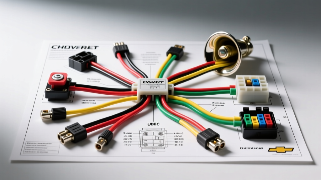
Introduction to the GMT800 Horn Circuit Architecture
Understanding the 2004 Chevy Silverado horn wiring diagram requires a deep dive into the GMT800 platform's electrical architecture. Unlike older vehicles where the horn button directly switches high-current power, the 2004 Silverado utilizes a multiplexed Body Control Module (BCM) logic circuit. When you press the steering wheel horn pad, you are not sending 12 volts to the horn; instead, you are completing a low-current ground path through the Steering Inflatable Restraint (SIR) module—commonly known as the clockspring. This signal is read by the BCM, which then triggers the Horn Relay located in the Underhood Bussed Electrical Center (UBEC).
This indirect routing protects the delicate steering wheel contacts from high-current arcing but introduces multiple failure points, including the clockspring, BCM logic gates, and the UBEC relay itself. Whether you are diagnosing a dead horn, replacing a damaged harness, or upgrading to high-decibel aftermarket air horns, mastering this schematic is mandatory for a reliable installation.
2004 Chevy Silverado Horn Wiring Diagram & UBEC Pinout
The heart of the factory horn circuit is the Micro ISO relay housed in the UBEC. Below is the definitive pinout table for the factory horn relay, detailing the exact OEM wire colors, AWG specifications, and circuit functions based on GM service documentation.
| Relay Pin | Cavity | OEM Wire Color | AWG Size | Circuit Function |
|---|---|---|---|---|
| 30 | UBEC C1 | Orange | 14 AWG | Constant Battery Feed (B+) from Mega Fuse |
| 87 | UBEC C3 | Dark Green | 14 AWG | Switched Output to Horn Assemblies |
| 85 | UBEC C2 | Dark Green/White | 18 AWG | Relay Coil Ground (Controlled by BCM) |
| 86 | UBEC C5 | Pink | 18 AWG | Ignition 1 (IGN1) Feed to Relay Coil |
Note: The horn assemblies themselves receive the Dark Green wire (Pin 87) and ground locally through their mounting brackets to the radiator core support (Ground Point G104).
Required Tools and Materials for Installation
To properly repair or upgrade the horn circuit without inducing future voltage drop or corrosion, you must use automotive-grade materials. Never use household solid-core wire or standard vinyl electrical tape.
- Wire: 14 AWG and 18 AWG SAE J1128 TXL (Cross-Linked Polyethylene) primary wire. TXL wire offers superior heat and chemical resistance compared to standard PVC wire (SAE J1128 Standard).
- Connectors: Heat-shrink butt splices with adhesive-lined interiors and Deutsch DT series connectors for aftermarket horn pigtails.
- Testing Equipment: Digital Multimeter (DMM) with millivolt resolution for voltage drop testing, and a GM-specific terminal extraction tool (J-38125 or equivalent) for UBEC repairs.
- Hardware: M6 flange nuts and star washers for chassis grounding.
Step-by-Step Horn Replacement and Wiring Guide
Step 1: Disable the SIR System and Disconnect Power
Because the horn switch is integrated into the steering wheel airbag assembly, safety is paramount. Disconnect the negative battery cable and isolate it. Wait a minimum of 60 seconds for the SDM (Sensing and Diagnostic Module) backup capacitors to discharge before probing any clockspring or steering column wiring.
Step 2: Test the Clockspring Continuity
Before tearing into the UBEC, verify the input signal. Access the base of the steering column and locate the horn switch signal wire (typically Yellow). Set your DMM to continuity mode. Place one probe on a known good chassis ground and the other on the Yellow wire terminal. Press the horn pad on the steering wheel. You should see near-zero resistance (under 1.0 ohm). If the circuit is open, your clockspring is fractured—a common GMT800 failure mode—and must be replaced before proceeding.
Step 3: Extract and Bench-Test the UBEC Relay
Open the Underhood Bussed Electrical Center and locate the Horn Relay. Pull the relay straight up using a gentle rocking motion. Using a 12V power supply, apply voltage to Pin 86 and ground Pin 85. You should hear a distinct mechanical click. Use your DMM to check continuity between Pin 30 and Pin 87 while the coil is energized. Resistance should be less than 0.2 ohms. If the relay clicks but shows high resistance across the switched contacts, the internal contacts are carbonized. Replace it with an OEM-spec Micro ISO relay (Littelfuse Automotive Relay Guide).
Step 4: Install New Horn Assemblies and Route Harness
Remove the lower radiator air deflector to access the factory horn bracket. Unbolt the M6 fastener securing the horn to the core support. Disconnect the 2-pin weatherpack connector. If installing upgraded dual-tone horns (e.g., Fiamm or Hella), you must construct a new parallel harness. Splice your new 14 AWG Dark Green TXL wire into the factory Dark Green output wire near the UBEC using an adhesive-lined heat shrink splice. Route the new harness along the factory headlight harness, securing it with UV-resistant nylon zip ties every 8 inches to prevent chafing against the radiator.
Step 5: Establish a Zero-Resistance Ground
The most overlooked step in the 2004 Chevy Silverado horn wiring diagram execution is the ground. The horns do not have a dedicated ground wire; they ground through the metal bracket to the steel core support. Scrape away all paint, primer, and surface rust from the mounting boss on the core support using a wire wheel. Apply a thin layer of dielectric grease to the star washer to prevent galvanic corrosion, then torque the M6 flange nut to 9 Nm (80 lb-in).
Troubleshooting Decision Tree: Symptom-Cause-Fix
Use this structured diagnostic tree to isolate electrical faults in the GMT800 horn circuit.
- Symptom: Horn does not sound, Airbag (SIR) light is illuminated on the dash.
- Cause: Clockspring internal ribbon cable fracture.
- Fix: Replace the Steering Wheel Position Sensor (SWPS) / Clockspring assembly. Recenter the new unit before installation to prevent immediate re-breakage.
- Symptom: Horn sounds weak, distorted, or pitches down when the engine is idling.
- Cause: Severe voltage drop on the Dark Green (Pin 87) circuit or corroded G104 ground point.
- Fix: Perform a voltage drop test. Place DMM probes on the battery positive post and the horn's input terminal while the horn is sounding. A reading above 0.5V indicates excessive resistance in the wire or UBEC relay contacts. Replace the 14 AWG run or clean the ground.
- Symptom: Horn works intermittently, only when the steering wheel is turned slightly off-center.
- Cause: Failing horn contact plate inside the steering wheel pad or worn clockspring contacts.
- Fix: Remove the driver airbag module (after battery disconnect) and inspect the copper contact pins for pitting. Clean with electrical contact cleaner or replace the horn pad assembly.
- Symptom: Horn relay clicks in the UBEC, but no sound from the horns.
- Cause: Open circuit between UBEC Pin 87 and the horn connector, or both horn diaphragms are seized from water intrusion.
- Fix: Backprobe the Dark Green wire at the horn connector with a test light. If power is present during relay activation, the harness is intact, and the horn assemblies must be replaced.
Expert Insights on GMT800 Electrical Quirks
When working with the 2004 Silverado, be aware that the BCM controls the horn relay ground (Pin 85) to enable a 'horn chirp' feature during lock/unlock sequences. If you are installing an aftermarket alarm or remote start system, do not tap directly into the Dark Green high-current wire. Instead, splice into the Dark Green/White (Pin 85) control wire using a 1N4004 diode to prevent back-feeding voltage into the BCM, which can fry the internal logic board and result in a $600+ replacement cost. Always respect the multiplexed nature of GMT800 electrical systems and rely on the precise wire colors and AWG ratings outlined in this 2004 Chevy Silverado horn wiring diagram guide to ensure a factory-quality repair.