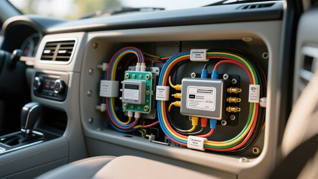
Introduction to Comfort Zone Auxiliary Heater Systems
Integrating an auxiliary cabin heater into a work truck, sleeper cab, or motorhome requires a precise understanding of high-amperage 12V DC circuits. The Comfort Zone heater wiring diagram outlines the integration of a high-output ceramic or hydronic heating element paired with a multi-speed blower motor. Unlike standard OEM HVAC systems that rely on engine coolant, these aftermarket 12V systems draw significant current directly from the vehicle's chassis battery or auxiliary house bank.
Improper wiring of these systems is a leading cause of voltage drop, melted insulation, and parasitic battery drain. This practical how-to installation guide breaks down the exact wire gauges, relay pinouts, and circuit protection requirements needed to safely deploy a Comfort Zone auxiliary heater. By adhering to SAE J1128 standards for low-tension primary cable, you ensure the wiring harness can withstand under-hood temperatures and continuous high-current loads without degradation.
Essential Tools and Wiring Specifications
Before beginning the installation, gather the correct materials. Using undersized wire or inferior connectors will result in severe voltage drop, causing the heater's internal thermal cutoff switches to trip prematurely. All primary wiring should utilize Cross-Linked Polyethylene (XLPE) insulation, such as GXL or TXL wire, which offers superior heat and abrasion resistance compared to standard PVC.
| Circuit Function | Wire Gauge (AWG) | OEM Color Code | Protection / Fuse | Connector Type |
|---|---|---|---|---|
| Main 12V+ Battery Feed | 10 AWG (GXL) | Red | 40A MAXI Blade | 3/8" Ring Terminal (Adhesive Heat Shrink) |
| Main Chassis Ground | 10 AWG (GXL) | Black | N/A | 3/8" Ring Terminal (Star Washer) |
| Ignition Signal (Coil Power) | 16 AWG (TXL) | Yellow | 5A ATO Blade | Weather-Pack Male Pin |
| Thermostat Switch (Coil Ground) | 18 AWG (TXL) | Blue | 2A ATO Blade | Deutsch DT Socket |
| Blower Motor High Speed | 12 AWG (GXL) | Orange | 20A ATO Blade | Weather-Pack Female Pin |
Decoding the Comfort Zone Heater Wiring Diagram
The core of the Comfort Zone heater wiring diagram relies on a heavy-duty ISO 5-pin automotive relay to isolate the high-amperage heating element from the low-amperage thermostat and ignition control circuits. This prevents the delicate cabin thermostat switch from arcing and failing under the 30+ amp load of the heating element.
ISO 5-Pin Relay Pinout Configuration
- Pin 30 (Common): Receives continuous 12V+ from the battery via the main 40A MAXI fuse. Use 10 AWG red wire.
- Pin 87 (Normally Open): Outputs 12V+ to the heater's main power terminal when the relay is energized. Use 10 AWG red wire.
- Pin 86 (Coil Power): Receives 12V+ only when the ignition is in the 'ON' or 'ACC' position. This ensures the heater cannot be left on when the vehicle is parked, preventing parasitic drain. Use 16 AWG yellow wire.
- Pin 85 (Coil Ground): Routes to the cabin thermostat switch. When the cabin temperature drops below the set point, the thermostat closes, completing the ground path and energizing the relay coil. Use 18 AWG blue wire.
- Pin 87a (Normally Closed): Unused in this specific heating application. Tape off and secure.
Calculating Voltage Drop for Long Cable Runs
In motorhomes and extended wheelbase trucks, the distance from the engine bay battery to the rear cabin heater can exceed 25 feet. According to standard electrical engineering principles, a 10 AWG copper wire carrying 35 amps over a 50-foot round-trip distance will experience a voltage drop of approximately 2.1 volts. If your alternator outputs 14.2V, the heater will only see 12.1V, which reduces heating efficiency and increases amperage draw, potentially overheating the wire.
To mitigate this, the comfort zone heater wiring diagram recommends upsizing the main feed to 8 AWG wire for any run exceeding 15 feet one-way. Always measure the actual voltage at the heater's Pin 87 terminal while the system is under full load to verify the drop is less than 3% (0.42V on a 14V system).
Step-by-Step Installation Procedure
Step 1: Routing and Prepping the Main Harness
Disconnect the negative battery terminal before beginning. Route the 10 AWG red and black wires from the battery location to the cabin heater mounting point. When passing through the firewall or bulkhead, you must use a rubber grommet to prevent sheet metal from slicing the XLPE insulation. Encase the entire under-hood run in split-loom tubing and secure it every 12 inches with UV-resistant zip ties. Never route high-amperage DC wires parallel to sensitive CAN-bus or audio signal wiring to prevent electromagnetic interference (EMI).
Step 2: Integrating the 40A MAXI Fuse and Relay
Install an inline MAXI fuse holder on the 10 AWG red wire within 18 inches of the battery positive terminal. This complies with ABYC and RVIA safety standards for overcurrent protection. Crimp the wire using a ratcheting wire crimper to ensure a gas-tight connection. Soldering is not recommended for high-vibration automotive environments, as solder wicks into the wire strands, creating a brittle point that will eventually snap. Instead, use adhesive-lined marine-grade heat shrink tubing to seal the crimp against moisture and corrosion.
Step 3: Connecting the Thermostat and Ignition Logic
Tap into an ignition-switched 12V+ source in the cab using a proper T-tap or, preferably, by adding a fused pigtail to an empty slot in the vehicle's fuse panel. Connect this to Pin 86 on the relay. Route the 18 AWG blue wire from Pin 85 to the Comfort Zone thermostat. The thermostat must be mounted on an interior wall away from direct sunlight, exterior draft sources, or the heater's own output vents to ensure accurate ambient temperature reading and proper hysteresis cycling.
Step 4: Establishing a True Chassis Ground
The most common failure point in aftermarket heater installations is a poor ground. Do not simply bolt the 10 AWG black ground wire to a random seat bracket. Locate a dedicated factory grounding stud on the chassis or seat frame. Remove the bolt, scrape away all paint and powder coating down to bare, shiny metal using a wire brush or sandpaper. Place a stainless steel star washer between the ring terminal and the bare metal to bite into the surface, then torque the bolt to the manufacturer's specification (typically 15-20 lb-ft for M8 hardware). Coat the finished connection with dielectric grease to prevent galvanic corrosion.
Common Wiring Failure Modes and Troubleshooting
Even with a perfect installation, environmental factors can cause issues. Use this diagnostic tree to troubleshoot common Comfort Zone heater faults:
- Symptom: Heater blower runs, but no heat is generated.
Cause: Voltage drop across the relay contacts or a tripped internal thermal fuse.
Fix: Use a multimeter to measure voltage at Pin 30 and Pin 87 while the system is active. If there is a difference greater than 0.5V, the ISO relay contacts are pitted and the relay must be replaced. Refer to Littelfuse high-current relay datasheets for heavy-duty alternatives with silver-nickel contacts. - Symptom: Heater turns on, but shuts off after 3 minutes.
Cause: Undersized wiring causing the internal thermal cutoff to trigger due to excessive amperage draw from low voltage.
Fix: Verify wire gauge and check for corrosion at the chassis ground point. Clean and retorque the ground. - Symptom: Parasitic battery drain overnight.
Cause: Wiring Pin 86 to a constant 12V+ source instead of an ignition-switched source, allowing the thermostat to cycle the heater indefinitely while parked.
Fix: Reroute Pin 86 to a verified ignition-switched circuit and test with a test light to ensure it powers down when the key is removed.
Authoritative References
For further technical specifications on automotive wire insulation and overcurrent protection, consult the following industry standards:
- SAE J1128: Low Tension Primary Cable - Society of Automotive Engineers standards for wire insulation temperature ratings and gauge sizing.
- Littelfuse MAXI Blade Fuse Specifications - Time-current characteristics for high-amperage automotive circuit protection.