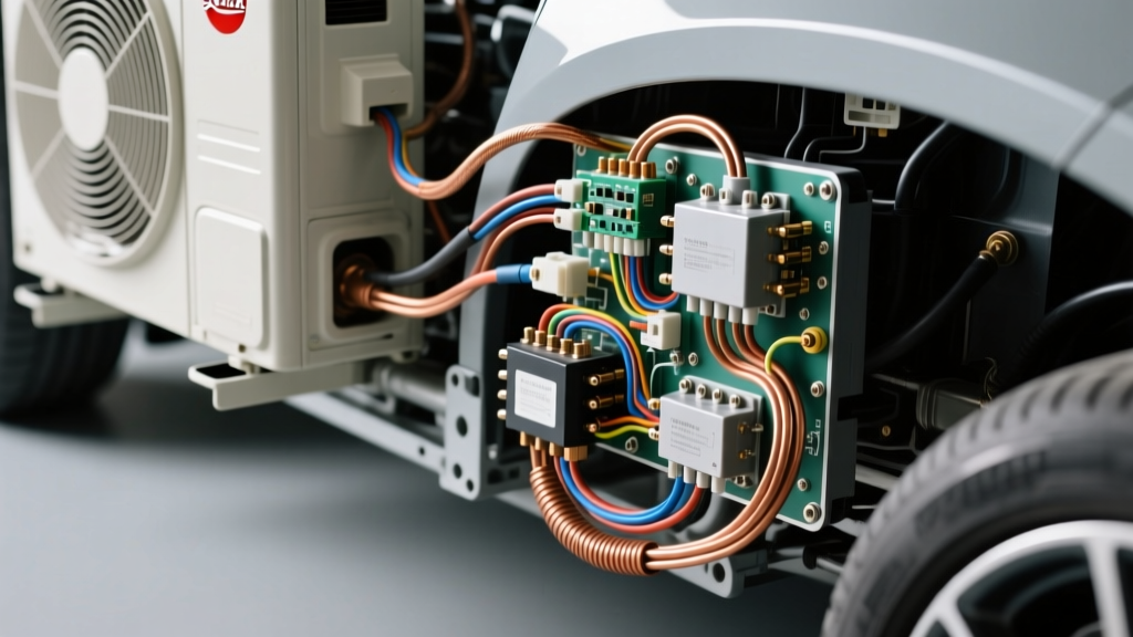
Bridging the Gap: Residential HVAC vs. Automotive EV Thermal Management
As the UK automotive sector rapidly transitions to electric vehicles (EVs), auto-electricians are increasingly encountering advanced thermal management systems. Modern EVs like the Tesla Model Y, Hyundai Ioniq 5, and Nissan Ariya utilize complex automotive heat pumps to scavenge ambient air and waste heat for cabin heating and battery conditioning. However, technicians searching for an air source heat pump wiring diagram UK databases provide often stumble upon residential MCS-certified home heating schematics rather than automotive EV thermal harnesses. While the thermodynamic principles—compressor, condenser, expansion valve, and evaporator—remain identical, the electrical architecture of a 400V or 800V DC automotive platform requires an entirely different diagnostic approach, toolset, and safety protocol.
This guide provides a comprehensive cost and tool requirements analysis for UK auto-electricians diagnosing EV heat pump compressors, control modules, and High Voltage Interlock Loop (HVIL) circuits, complete with OEM-level pinout data and waveform diagnostic strategies.
Cost & Tool Requirements Matrix for EV Heat Pump Diagnostics
Diagnosing an automotive air-source heat pump requires bridging low-voltage (LV) communication networks and high-voltage (HV) power delivery. Below is the essential tooling matrix and associated cost analysis for a UK-based independent EV specialist.
| Equipment / Service | Specification / Standard | Est. Cost (GBP) | Diagnostic Purpose |
|---|---|---|---|
| Automotive Oscilloscope | PicoScope 4425A (4-Channel) | £1,399 | Decoding LIN/CAN bus waveforms to verify compressor speed commands and module handshakes. |
| HV Multimeter | Fluke 87V (CAT III 1000V / CAT IV 600V) | £425 | Verifying LV 12V feeds and checking HVIL loop continuity without risking meter failure. |
| Insulated Hand Tools & Gloves | Class 0 (1000V) Gauntlets & VDE Drivers | £185 | Mandatory safety gear per IMI EV Certification standards before HV connector removal. |
| OEM LV Wiring Harness | Heat Pump Control Module Pigtail (7-Pin) | £145 - £280 | Replacement of degraded LV connectors suffering from moisture ingress or terminal fretting. |
| Refrigerant Handling (HFO-1234yf) | Automotive Recovery & Vacuum Station | £2,500+ | Required if the heat pump compressor seal fails or HV lines require physical rerouting. |
Technical Deep Dive: EV Heat Pump Compressor Pinout & Wiring Specs
Unlike residential ASHPs that rely on 230V single-phase or 400V three-phase AC mains, automotive heat pump compressors are driven by an integrated internal inverter that converts the vehicle's DC traction battery voltage into three-phase AC. The external wiring harness is divided into a High Voltage (HV) power supply and a Low Voltage (LV) control connector.
High Voltage (HV) Power Connector
The HV connector supplies DC power directly from the Power Distribution Unit (PDU). Warning: Never probe these terminals without SAE J2843 compliant isolation procedures.
- Pin A (HV+): 35mm² (approx. 2 AWG) Orange shielded cable. Supplies 400V-800V DC.
- Pin B (HV-): 35mm² (approx. 2 AWG) Orange shielded cable. Main DC ground return.
- HVIL Loop: Integrated into the connector housing. Uses 0.35mm² (22 AWG) Orange wire. Breaking the physical connector mating severs the 5V/12V HVIL reference, instantly disabling the inverter.
Low Voltage (LV) Control Connector (7-Pin)
The LV harness manages thermal logic, CAN bus networking, and LIN bus motor control. Below is the standard pinout for a generic Hanon/Denso EV heat pump compressor module.
| Pin | Function | Wire Color | Gauge (mm² / AWG) | Signal Type |
|---|---|---|---|---|
| 1 | 12V Battery Feed (B+) | Red | 2.5mm² / 14 AWG | Constant 12V (Fused) |
| 2 | Chassis Ground | Black | 2.5mm² / 14 AWG | Ground (< 0.05Ω to chassis) |
| 3 | LIN Bus Data | Green/White | 0.5mm² / 20 AWG | 12V PWM (19.2 kbps) |
| 4 | CAN High (PT-CAN) | Yellow | 0.5mm² / 20 AWG | Differential (2.5V - 3.5V) |
| 5 | CAN Low (PT-CAN) | Brown | 0.5mm² / 20 AWG | Differential (1.5V - 2.5V) |
| 6 | HVIL In | Orange | 0.35mm² / 22 AWG | 5V Reference |
| 7 | HVIL Out | Orange | 0.35mm² / 22 AWG | Return to BMS/PDU |
Waveform Analysis & Diagnostic Decision Tree
When an EV presents a thermal management fault (e.g., cabin heating failure or battery derating due to thermal limits), the OBD2 port will often yield a generic U-code such as U013A (Lost Communication with HVAC Control Module) or P0A0F. Relying solely on code readers is insufficient. Pico Technology Automotive recommends back-probing the LV connector to analyze the physical layer of the communication networks.
Step 1: Verify the LIN Bus Command Signal
The Thermal Management Module (TMM) uses the LIN bus to command the compressor's internal inverter. Connect your oscilloscope to Pin 3 (Green/White).
- Normal State: Hidden (recessive) state at 12V. Dominant state pulls to ground (0V).
- Fault Condition: If the waveform is a flat 12V line, the TMM is not sending a speed command, or the LIN pull-up resistor inside the compressor inverter has failed open.
- Fault Condition: If the signal is stuck at 0V, there is a short to ground in the 0.5mm² Green/White wire, or the compressor internal logic board has shorted the transceiver.
Step 2: Test the HVIL Continuity
If the LIN bus is active but the compressor refuses to draw HV current, the inverter may be inhibiting operation due to an HVIL fault. Using a CAT III rated multimeter, measure the voltage drop across Pins 6 and 7 with the connector mated and the vehicle in 'Ready to Drive' mode.
- Expected Reading: A continuous 5V or 12V reference (depending on OEM architecture). A voltage drop greater than 0.5V across the mated pins indicates terminal fretting or corrosion inside the LV connector housing, a common failure point in UK climates due to road salt and moisture ingress.
Step 3: CAN Bus Termination Check
If the scanner cannot see the Heat Pump Module on the network, measure the resistance between Pin 4 (CAN High) and Pin 5 (CAN Low) with the vehicle powered down and the 12V battery disconnected. You should read exactly 60Ω (indicating two 120Ω termination resistors in parallel). A reading of 120Ω means the heat pump module's internal termination resistor has failed or the harness is broken.
Summary for UK Auto-Electricians
While the search intent for residential ASHP schematics is high, the automotive equivalent demands rigorous adherence to high-voltage safety and high-speed network diagnostics. Investing in a 4-channel oscilloscope and proper IMI-certified HV safety gear is non-negotiable. By understanding the specific 0.5mm² LIN/CAN architectures and 35mm² HV delivery systems outlined above, technicians can accurately diagnose EV thermal failures, avoid unnecessary OEM module replacements, and safely restore vehicle range and cabin comfort.