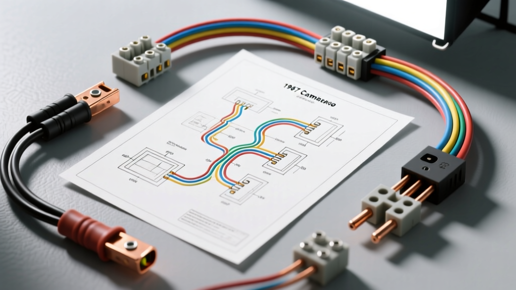
Decoding the 1967 Camaro Wiring Diagram PDF: A Restoration Blueprint
The first-generation Chevrolet F-body is an automotive icon, but its 50-year-old electrical system is often a labyrinth of brittle insulation, corroded terminals, and previous owner "fixes." When undertaking a complete electrical restoration, securing an accurate 1967 camaro wiring diagram pdf is only the first step. The factory Assembly Instruction Manual (AIM) and the Chevrolet Service Manual schematics provide the theoretical roadmap, but translating those 2D lines into a reliable, fire-safe 3D harness requires specialized tooling, an understanding of General Motors' 1960s color-code logic, and a realistic budget.
This comprehensive cost and tool requirements analysis breaks down exactly what you need to successfully rewire a 1967 Camaro, whether you are restoring a numbers-matching SS/RS clone to factory specifications or updating a driver-quality coupe with modern fused circuits.
Essential Tooling for Gen-1 GM Electrical Work
You cannot reliably crimp or extract 1960s Packard and Delco terminals using modern generic crimpers. Using the wrong tool deforms the terminal tangs, leading to loose connections inside the fuse block or bulkhead connector, which causes high resistance and subsequent heat.
Terminal Crimpers & Extractors
- Packard 56 Series Crimper: The 1967 Camaro fuse block and headlight switch primarily use Packard 56 terminals. You need a crimper specifically calibrated for the .056-inch terminal width (such as the Delphi/Packard 56 specific die or a high-quality equivalent like the Pico 8822PT).
- Weather Pack / Metri-Pack Crimpers: If you are modifying the schematic to add modern relayers for headlights or fuel injection, you will need ratcheting crimpers for 16-14 AWG and 12-10 AWG sealed terminals.
- Terminal Extraction Picks: The 1967 Camaro firewall bulkhead connector requires a specific flat-blade extraction tool to depress the locking tangs without snapping 50-year-old brittle plastic housings. A set of micro-picks and a dedicated Packard 56 extraction tool are mandatory.
Wire Processing & Testing
- Precision Wire Strippers: Klein Tools 11055 (for 10-18 AWG) or equivalent. Stripping the insulation without nicking the copper strands is critical for maintaining the ampacity rating defined in SAE J1128 standards for low-tension primary cables.
- Digital Multimeter (DMM):strong> Essential for performing voltage drop tests across the bulkhead connector and verifying continuity against your 1967 camaro wiring diagram pdf before applying battery power.
- Heat Gun & Adhesive-Lined Heat Shrink: For sealing soldered splices and protecting the main battery feed wire from under-hood thermal degradation.
Cost Breakdown: OEM Restoration vs. Aftermarket Updates
The cost of rewiring a 1967 Camaro varies wildly based on your end goal. Concours restorations demand exact cloth-braided or PVC-jacketed OEM reproduction harnesses, while pro-touring builds benefit from updated, fused aftermarket kits.
| Harness Type | Manufacturer Examples | Estimated Cost (USD) | Best Application |
|---|---|---|---|
| OEM Exact Reproduction | M&H Electric Fabricators, Lectric Limited | $900 - $1,400 | Concours judging, numbers-matching restorations, factory A/C & RS packages. |
| Direct-Fit Updated | American Autowire (Classic Update) | $550 - $750 | Restomods, high-amp alternator upgrades, modern stereo integration. |
| Universal Pro-Touring | Painless Performance, Centec | $350 - $500 | Custom tube-chassis, LS-swapped builds requiring custom routing and modern blade fuses. |
| DIY Bulk Wire & Loom | Waytek Wire, generic loom, DIY crimping | $150 - $250 | Budget builds, patching specific circuits, advanced fabricators with ample time. |
Note: Costs do not include specialized tools, replacement bulkhead housings, or new switches (headlight, ignition, wiper), which can add $300-$500 to the project.
Critical Wire Gauges & Factory Color Codes (1967 Spec)
When reading your 1967 camaro wiring diagram pdf, the line thickness often denotes the wire gauge, while the text abbreviations denote the color. General Motors utilized a standardized color-coding system in 1967 that makes troubleshooting logical once you understand the patterns (e.g., Light Blue is almost always Right Front Turn, Dark Blue is Left Front Turn).
| Circuit Function | AWG Size | Factory Wire Color | Schematic Abbreviation |
|---|---|---|---|
| Battery to Horn Relay / Junction | 10 AWG | Red (or Red w/ White Tracer) | RED / RED-WHT |
| Alternator to External Regulator (Field) | 12 AWG | Blue | BLU |
| Headlight Switch to Dimmer Switch | 12 AWG | Brown | BRN |
| Ignition Switch to Coil / Ballast Resistor | 14 AWG | Pink (or Pink w/ Black) | PNK |
| Ignition Switch to Starter Solenoid (Crank) | 12 AWG | Purple | PPL |
| Right Front Turn Signal / Parking | 14 AWG | Light Blue | LT BLU |
| Left Front Turn Signal / Parking | 14 AWG | Dark Blue | DK BLU |
| Backup Lamps (from Neutral Safety/4spd) | 14 AWG | Light Green | LT GRN |
Known Failure Points & Troubleshooting the Schematic
Even with a perfect PDF schematic, the physical execution on a 1967 F-body presents specific engineering flaws that must be addressed during the rewire process.
1. The Firewall Bulkhead Connector Voltage Drop
The 1967 Camaro routes almost the entire front lighting harness through a single multi-cavity bulkhead connector on the passenger side firewall. Over decades, moisture intrusion causes micro-corrosion on the Packard 56 terminals. According to Ohm's Law, increased resistance at this junction causes a severe voltage drop. If you measure 13.5V at the horn relay but only 10.5V at the headlight dimmer switch, the bulkhead is the culprit.
The Fix: Extract every pin using the proper tool, clean the male and female terminals with electrical contact cleaner and a fiberglass scratch pen, and apply a dielectric grease (like Nyogel 760G) before re-seating them. If the plastic housing is warped from heat, you must source a reproduction bulkhead housing from restoration suppliers like Classic Industries.
2. Headlight Switch Connector Melting
The factory headlight switch in the '67 Camaro draws the entire amperage of the headlights, parking lights, and taillights directly through the switch contacts. The main battery feed wire (typically 12 AWG Red) enters a specific cavity on the switch plug. High resistance here generates immense heat, literally melting the plastic connector body and fusing it to the switch.
The Fix: While an OEM reproduction harness will replicate this flaw, the modern engineering solution is to use the factory headlight switch only as a low-amperage trigger for high-current automotive relays (Bosch-style 30A/40A relays) mounted near the horn relay. This keeps the high-current 10 AWG and 12 AWG loads out of the dashboard entirely, a modification easily mapped out by adapting your 1967 camaro wiring diagram pdf to include relay trigger circuits.
3. Ignition Switch 'Pink' Wire Degradation
The 12V ignition feed (Pink wire) powers the wiper motor, heater blower, gauges, and coil. The terminal at the ignition switch is prone to loosening. A loose connection here will cause the dash gauges to flicker or the engine to stall when hitting bumps. Always replace the ignition switch pigtail with a new, tight-fitting connector during a rewire.
Schematic Sources & Authoritative References
To ensure your restoration meets factory or safe aftermarket standards, rely on verified documentation rather than forum guesswork.
- SAE International: Adhere to SAE J1128 guidelines for low-tension primary cable sizing to ensure your wire gauge matches the circuit's maximum amperage draw, preventing harness fires.
- M&H Electric Fabricators: The definitive authority on OEM GM wiring reproduction. Their technical bulletins provide invaluable insights into factory tape-wrapping methods and correct cloth-braided loom applications for concours judging (wiringharness.com).
- Chevrolet 1967 Camaro AIM (Assembly Instruction Manual): While not a traditional "wiring diagram," the AIM shows the exact physical routing, clip placements, and tape-wrap locations required to make the harness look as it did on the Norwood or Van Nuys assembly line.
Conclusion
Rewiring a first-generation Camaro is a meticulous process that bridges the gap between 1960s manufacturing and modern electrical reliability. By investing in the correct Packard 56 crimping tools, understanding the financial differences between OEM and updated harnesses, and proactively engineering out known failure points like the bulkhead voltage drop, you can ensure your F-body's electrical system is as robust as its V8 powertrain. Keep your 1967 camaro wiring diagram pdf close, verify every circuit with a multimeter, and never compromise on terminal crimp quality.