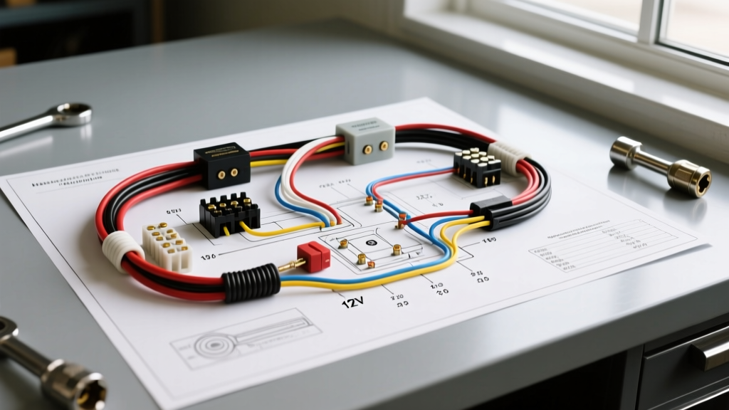
The 1955 Electrical Revolution: Understanding the 12-Volt Shift
When you sit down to study a 55 Chevy wiring diagram, you are looking at a pivotal moment in automotive history. The 1955 model year marked Chevrolet's first transition from 6-volt to 12-volt electrical systems for passenger cars, including the iconic Bel Air, 150, and 210 models. For a beginner, this is the most critical fundamental to grasp: your classic Chevy is designed around a 12-volt architecture, which means thinner wires, different bulb ratings, and specific voltage regulators compared to the 1954 and earlier models.
Understanding the schematic is not just about connecting point A to point B; it is about respecting the current capacity and voltage drops inherent in a 70-year-old harness. Whether you are restoring a numbers-matching 265 cubic-inch V8 or restomodding with an LS swap, mastering the factory diagram is your baseline for a reliable electrical system.
How to Read Your 55 Chevy Wiring Diagram
Factory assembly manuals and aftermarket reproduction diagrams use specific symbology. A standard schematic is a logical map, not a physical routing guide. This means a wire drawn at the top left of the page might physically route under the carpet and through the firewall in your actual vehicle.
- Solid Lines: Represent continuous, unbroken copper wire.
- Dashed Lines: Indicate mechanical linkages or internal switch connections (like the internal wiper switch park circuit).
- Ground Symbols: The 1955 Chevy relies heavily on chassis grounding. The diagram will show components grounding to the engine block or body tub, meaning the metal itself completes the circuit back to the battery negative terminal.
- Splices and Connectors: Look for black dots at line intersections, which denote a soldered or crimped splice, versus lines that simply cross over one another without a dot.
Essential Wire Gauge and Color Code Specifications
Using the correct American Wire Gauge (AWG) is vital to prevent voltage drop and electrical fires. The SAE J1128 standard dictates that as wire diameter decreases, the AWG number increases. Below is the benchmark specification chart for a stock 1955 Chevy 12-volt passenger car.
| Circuit Application | Recommended AWG | Factory OEM Wire Color | Max Amp Load (Approx) |
|---|---|---|---|
| Battery to Starter Solenoid | 1/0 or 2 AWG | Black (or Red for positive ground conversions) | 250+ Amps (Cranking) |
| Alternator/Generator Charge Wire | 10 AWG | Red | 30 - 40 Amps |
| Headlight Feed (Main) | 12 AWG | Red | 20 Amps |
| Headlight Low/High Beam Branches | 14 AWG | Tan (Low) / Light Green (High) | 10 Amps per side |
| Tail Lights and Parking Lights | 16 AWG | Brown (Tail) / Dark Green (Stop) | 5 Amps |
| Instrument Cluster and Gauges | 18 AWG | Pink (Ignition feed) / Dark Blue (High beam indicator) | 3 Amps |
Note: Always refer to a trusted 1955 Chevrolet Assembly Manual for exact plant-specific color variations, as mid-year production changes did occur.
Core Circuit Breakdowns for Beginners
1. Headlights and the Floor Dimmer Switch
The 1955 Chevy utilizes a floor-mounted dimmer switch to toggle between high and low beams. This is a frequent failure point due to moisture and dirt intrusion. The switch features three spade terminals:
- Terminal 1 (Power In): Receives 12V from the headlight switch via a 12 AWG Red wire.
- Terminal 2 (Low Beam Out): Sends power to the low beam filaments via a 14 AWG Tan wire.
- Terminal 3 (High Beam Out): Sends power to the high beam filaments via a 14 AWG Light Green wire. A branch off this wire (Dark Green, 18 AWG) routes to the dash indicator light.
Beginner Tip: When replacing the floor switch, use dielectric grease on the spade connectors and ensure the rubber boot is fully seated to prevent corrosion-induced voltage drop.
2. The Ignition Switch and Starter Solenoid
The ignition switch on the dash acts as the master gatekeeper. It routes 12V to the coil, gauges, and accessories. When you turn the key to 'Start', power flows via a Purple (or Yellow, depending on build date) wire to the 'S' terminal on the starter solenoid.
Crucially, the solenoid also features an 'R' terminal. During cranking, the starter draws massive amperage, which can drop system voltage below 9 volts. The 'R' terminal bypasses the ignition ballast resistor (or resistance wire), sending a full 12V directly to the positive side of the ignition coil to ensure a hot spark while the engine is turning over. If your Chevy starts but dies the moment you release the key from the 'Start' position, you have likely lost the 'R' terminal circuit or your ballast resistor is open.
3. Instrument Cluster and the IVR Trap
This is where most beginners destroy their gauges. While the 1955 Chevy operates on a 12-volt system, the original thermal fuel and temperature gauges are designed to operate on 6 volts. To bridge this gap, Chevrolet installed an Instrument Voltage Regulator (IVR) on the back of the speedometer.
The IVR is a mechanical, pulsing switch that rapidly connects and disconnects 12V, creating an average output of roughly 6 volts. Never apply direct 12V to the sending unit side of the fuel or temp gauges. Doing so will instantly peg the needles to the maximum reading, overheat the internal bimetallic strips, and permanently ruin the vintage gauges. If both your fuel and temp gauges read empty or full simultaneously, the IVR has likely failed or lost its ground.
Real-World Troubleshooting: The Bad Ground Backfeed
One of the most common and confusing issues for novice classic Chevy owners is the 'phantom dash light' syndrome. You press the brake pedal, and suddenly your dashboard instrument lights illuminate, even though the headlight switch is off.
The Cause: The 1955 Chevy tail lights use 1157 dual-filament bulbs. One filament is for the tail light (running light), and the brighter filament is for the brake/turn signal. Both filaments share a single ground path through the metal bulb housing to the car body. If the tail light housing is rusted or lacks a dedicated ground strap, the brake light current cannot reach the chassis. Instead, it flows backward through the tail light filament, up the Brown tail light wire, and into the headlight switch, illuminating the dash bulbs in reverse.
The Fix: Scrape the paint and rust from the tail light housing mounting points. For a permanent solution, solder an 18 AWG Black ground wire directly to the bulb socket base and bolt it to a clean, bare metal spot on the chassis. This eliminates reliance on rusty sheet metal for the return path.
Upgrading to a Modern Alternator
Many beginners upgrading their 55 Chevy will swap the stock generator for a GM 10SI or 12SI alternator. If you use a 1-wire alternator, you must run a heavy 10 AWG charge wire directly from the alternator BAT terminal to the battery positive or starter solenoid. However, 1-wire alternators require high RPMs to 'excite' and begin charging. For street driving, a 3-wire setup is superior. Connect the 'L' terminal to your dash GEN/ALT warning light (which provides the initial excitation current), and connect the 'F/S' sense terminal directly to the main junction block near the horn relay to ensure accurate voltage regulation based on actual system demand, not just alternator output.
Authoritative Resources for Further Study
To master your vehicle's electrical system, always cross-reference your physical harness with factory documentation. We highly recommend consulting the Tri-Five Chevy Technical Archives for community-verified wiring corrections, and keeping a printed copy of the original 1955 Chevrolet Passenger Car Shop Manual in your garage. Understanding the logic behind the diagram transforms wiring from a frustrating chore into a rewarding aspect of your classic car restoration.