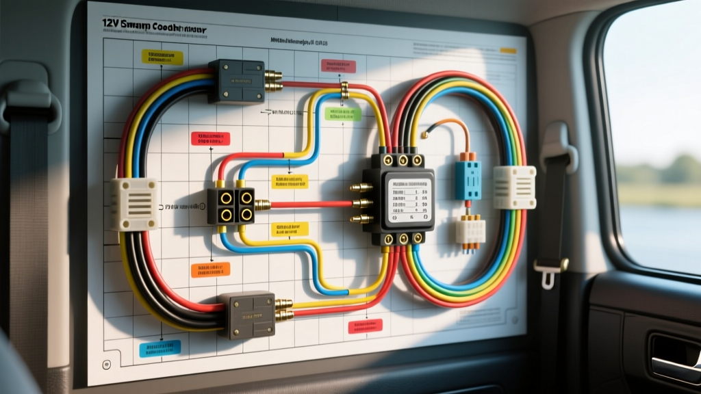
12V DC Evaporative Cooling: Beyond Standard HVAC
When outfitting heavy-duty truck sleeper cabs, overland expedition vehicles, or heavy machinery with auxiliary climate control, traditional compressor-based air conditioning is often impractical. Engine-off cooling requires massive inverter setups or dedicated Auxiliary Power Units (APUs). For dry climates, a 12V DC evaporative cooler offers a highly efficient alternative. However, integrating these systems requires a precise wiring diagram for swamp cooler setups to handle the unique inductive loads of DC blower motors and water pumps without triggering voltage drops or draining the vehicle's crank battery.
This advanced technical guide details the electrical architecture, relay logic, wire gauge specifications, and diagnostic protocols required to safely install and integrate a 12V automotive-grade swamp cooler into a vehicle's auxiliary power network.
System Architecture: Blower and Pump Loads
Unlike residential AC units, a 12V vehicle swamp cooler relies on two distinct electrical loads that must be managed independently but triggered synchronously:
- The Blower Motor: Typically a 12V DC brushless centrifugal fan. While nominal draw is usually between 8A and 12A, the startup surge (inrush current) can spike to 18A-22A for the first 200 milliseconds. This inductive load generates significant electromagnetic interference (EMI) and inductive kickback upon shutdown.
- The Water Pump: A 12V submersible or inline diaphragm pump responsible for saturating the cooling media. Nominal draw is lower (2A-5A), but pumps are highly sensitive to voltage drop. A drop below 11.5V can cause pump cavitation, leading to dry media pads and complete loss of cooling efficiency.
Because of these distinct characteristics, running both components on a single switch and relay circuit is a critical failure point. A proper wiring diagram for swamp cooler installations mandates isolated relay circuits for the blower and the pump, unified only at the control switch level.
Comprehensive Wiring Schematic Path
Below is the node-by-node schematic path for a robust, automotive-grade 12V swamp cooler harness. This assumes integration with an auxiliary deep-cycle battery bank or a dedicated DC distribution block.
Primary Power Distribution
- Source: Auxiliary Battery Positive Terminal.
- Overcurrent Protection: 40A ANL Fuse mounted within 7 inches of the battery terminal (per ABYC and SAE heavy-duty standards).
- Main Trunk: 8 AWG SXL (Cross-Linked Polyethylene) wire routed through a firewall grommet to a sealed marine-grade distribution block.
Relay Branching
From the distribution block, the 8 AWG trunk splits into two 10 AWG pigtails, each feeding Pin 30 of two separate 40A SPDT (Single Pole Double Throw) Bosch-style automotive relays. One relay controls the blower; the second controls the water pump.
Control Circuit Logic
A single 18 AWG control wire runs from an ignition-switched or auxiliary-switched 12V source to a dashboard-mounted DPST (Double Pole Single Throw) toggle switch. The switch splits the signal, sending 12V to Pin 86 of both relays simultaneously. Pins 85 of both relays are tied to a dedicated, clean chassis ground.
Component Specification and AWG Chart
Selecting the correct wire gauge is critical. Using standard copper wire tables without accounting for the high-temperature environment of an engine bay or the voltage drop over long cable runs to a sleeper cab will result in blower motor overheating. The table below outlines the exact specifications required for a 15-foot cable run.
| Circuit Segment | AWG Size | Wire Insulation Spec | Max Amperage | Fuse / Breaker Rating |
|---|---|---|---|---|
| Battery to Distribution Block | 8 AWG | SAE J1128 Type SXL (125°C) | 40A | 40A ANL Fuse |
| Block to Relay (Pin 30) | 10 AWG | SAE J1128 Type GXL (125°C) | 30A | Protected by Main ANL |
| Relay (Pin 87) to Blower Motor | 12 AWG | TXL (Thin-wall, 125°C) | 20A | 15A Auto-Reset Circuit Breaker |
| Relay (Pin 87) to Water Pump | 14 AWG | TXL (Thin-wall, 125°C) | 10A | 5A ATO Blade Fuse |
| Control Switch to Relay (Pin 86) | 18 AWG | GXL Primary Wire | 3A | Protected by Switch Rating |
Standard SPDT Relay Integration and Flyback Suppression
Automotive environments are electrically noisy. When the dashboard switch is turned off, the collapsing magnetic field in the relay coils (Pins 85 and 86) generates a high-voltage reverse spike (inductive kickback). This spike can arc across the switch contacts, degrading the dashboard toggle switch over time, or feed back into sensitive vehicle ECU networks if the control wire shares a conduit with CAN bus wiring.
Expert Implementation: Install a 1N4001 flyback diode across Pins 85 and 86 of each relay. The silver band (cathode) must face Pin 86 (the positive trigger side). This creates a closed loop for the inductive spike to dissipate safely, protecting your vehicle's control modules and extending the life of the physical switch. For further EMI suppression on the blower motor itself, solder a 0.1μF ceramic capacitor directly across the motor's positive and negative terminals at the motor housing to filter high-frequency brush/commutator noise.
Dual-Battery Isolation and APU Integration
A common catastrophic mistake in auxiliary 12V swamp cooler installs is wiring the system directly to the vehicle's primary starting battery. A 15A continuous draw will drain a standard Group 31 starting battery below the 11.8V threshold required to crank a heavy-duty diesel engine in a matter of hours.
Your wiring diagram must incorporate a battery isolation mechanism. For modern heavy-duty trucks, integrate the swamp cooler's main power feed into the output side of a DC-DC Battery Charger or a Voltage Sensitive Relay (VSR). This ensures the swamp cooler only draws from the secondary deep-cycle auxiliary bank, and the VSR will automatically disconnect the auxiliary load if the alternator stops charging, preserving the crank battery. Always reference the SAE J1113 guidelines for electromagnetic compatibility when routing high-amperage DC lines near the vehicle's primary ECM harness.
Diagnostic Troubleshooting Tree
When a 12V swamp cooler fails in the field, the issue is rarely the cooler itself; it is almost always a voltage drop or grounding failure. Use this decision tree to diagnose the system:
- Symptom: Blower runs, but air is not cold / media pads are dry.
- Cause: Water pump cavitation or failure due to voltage drop.
- Diagnostic Step: Measure voltage directly at the pump terminals while the system is under load. If voltage reads below 11.5V, trace the 14 AWG wire back to the relay.
- Fix: Replace corroded spade connectors with adhesive-lined heat shrink crimps. Ensure the pump ground is not daisy-chained to the blower motor ground.
- Symptom: Blower motor surges or pulses rhythmically.
- Cause: The control module is entering low-voltage protection mode, or the main 8 AWG trunk is undersized/damaged.
- Diagnostic Step: Perform a voltage drop test across the 40A ANL fuse and the main distribution block connections.
- Fix: Clean terminal oxidation with a wire brush and apply dielectric grease. Torque ANL fuse nuts to manufacturer spec (usually 45 in-lbs) to prevent micro-arcing.
- Symptom: Dashboard switch melts or becomes hot to the touch.
- Cause: The switch is wired to carry the primary motor load instead of just the relay coil trigger.
- Fix: Rewire immediately. The switch must only handle the <1A load of the relay coils (Pins 86). Consult the Bosch Automotive Relays Handbook for proper SPDT load-side routing.
Grounding Protocols for Aluminum and Fiberglass Cabs
Many modern heavy-duty truck sleeper cabs and RV shells utilize aluminum framing or fiberglass composites. You cannot use the cab structure as a common ground bus. You must run a dedicated 8 AWG ground wire from the auxiliary battery negative terminal directly to a centralized negative bus bar inside the cab. All swamp cooler grounds (Pump Pin 85, Blower Pin 85, and motor negative) must terminate at this isolated bus bar. Attempting to ground to an aluminum cab rail without using a specialized star washer to bite through the anodized coating will result in high-resistance grounds, leading to erratic pump behavior and potential galvanic corrosion of the cab chassis.
Conclusion
Executing a flawless 12V swamp cooler installation requires treating the system not as a simple accessory, but as a high-draw auxiliary appliance. By adhering to strict AWG sizing, isolating inductive loads via SPDT relays, employing flyback diodes, and integrating proper dual-battery isolation, you ensure reliable, engine-off cooling in the harshest off-grid environments. For further reading on low-voltage RV and truck wiring standards, refer to the RV Industry Association (RVIA) low-voltage electrical codes and SAE heavy-duty wiring standards.