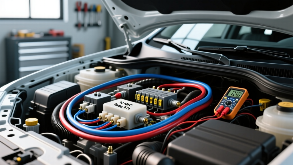
The Danger of Residential Diagrams in Automotive Applications
When upfitting work trucks, camper vans, or off-road rigs with auxiliary cabin heating, searching for a standard space heater wiring diagram often leads to dangerous residential 120V AC schematics. Automotive electrical systems operate on 12V or 24V DC, meaning the amperage draw for a high-output PTC (Positive Temperature Coefficient) ceramic space heater or a diesel-fired glow plug system is exponentially higher than household appliances. A 300W residential heater draws a mere 2.5 amps at 120V. A 300W 12V automotive space heater draws 25 amps continuously. Applying residential wiring logic to a 12V DC environment guarantees melted insulation, voltage drop, and catastrophic electrical fires.
This comprehensive cost and tool requirements analysis breaks down exactly what is required to safely execute an automotive-grade space heater wiring diagram. We will cover the precise AWG sizing, Bosch-style relay pinouts, specialized crimping tools, and the true financial investment required to build a reliable auxiliary heating circuit that meets SAE J1128 Low Tension Primary Cable standards.
12V Auxiliary Space Heater Wiring Diagram Architecture
A safe automotive space heater wiring diagram isolates the high-amperage load circuit from the low-amperage control circuit. Because high-draw PTC heaters can pull upwards of 30A upon initial cold-start (before the ceramic element heats up and resistance increases), a direct-to-switch wiring method will melt standard toggle switches within minutes. You must use an electromechanical relay or a solid-state contactor.
Standard Bosch-Style Relay Pinout Configuration
- Pin 30 (Input Power): 10 AWG Red wire routed directly from the battery positive terminal or primary bus bar, protected by a 40A MEGA fuse.
- Pin 87 (Output Load): 10 AWG Yellow wire routed to the positive terminal of the space heater.
- Pin 86 (Control Trigger): 18 AWG Blue wire connected to a dash-mounted toggle switch (sourced from an ignition-switched 12V fuse to prevent battery drain).
- Pin 85 (Control Ground): 18 AWG Black wire grounded to a clean, unpainted chassis point.
- Pin 87a (Unused): Taped back or capped; used only for SPDT (Single Pole Double Throw) switching applications.
The heater's negative terminal must be grounded using a 10 AWG Black wire with a marine-grade adhesive heat-shrink ring terminal, bolted directly to bare metal. Never rely on seat brackets or painted sheet metal for high-amperage grounding.
Comprehensive Tool Requirements Analysis
Executing this space heater wiring diagram requires more than a basic pair of pliers. Automotive environments subject wiring to severe vibration, thermal cycling, and moisture. The tools you use dictate the longevity of the crimp connections.
1. Precision Wire Stripping and Crimping
Standard insulated butt connectors and cheap ratchet crimpers are insufficient for the 10 AWG wires feeding a space heater. You must invest in open-barrel or heavy-duty closed-barrel crimpers. For the heater connection, utilizing a Deutsch DT series or Weather-Pack connector is mandatory to seal out moisture. A proper ratcheting crimper for these terminals costs between $60 and $120 but ensures a gas-tight crimp that prevents oxidation and subsequent resistance heating.
2. Thermal Diagnostics and Voltage Drop Testing
A digital multimeter (DMM) is required to test for voltage drop. According to Blue Sea Systems Circuit Wizard guidelines, a 12V circuit should not exceed a 3% voltage drop (0.36V) across the entire length of the wire run. Furthermore, an entry-level thermal imaging camera (like the FLIR ONE) is an invaluable diagnostic tool. After running the space heater for 15 minutes, scan the relay, fuse holder, and ground points. Any glowing hot spots indicate high resistance and a failing crimp.
3. Marine-Grade Heat Shrink
Standard PVC electrical tape will unspool in a hot engine bay or under a dashboard exposed to summer sun. Dual-wall, adhesive-lined polyolefin heat shrink is required for all ring terminals and splices. The inner adhesive melts and seals the wire strands against capillary corrosion.
Cost Breakdown: Building a Safe 12V Heater Circuit
Cutting corners on high-draw auxiliary circuits is a primary cause of vehicle fires. Below is a realistic cost analysis for sourcing high-quality, automotive-grade components for a 300W (25A) space heater wiring diagram.
| Component | Specification / Rating | Estimated Cost (USD) |
|---|---|---|
| Primary Wire (10 AWG) | SAE J1128 GXL, Pure Copper (25 ft) | $35.00 |
| Control Wire (18 AWG) | TXL Primary Wire, Multi-color (10 ft) | $8.00 |
| Overcurrent Protection | 40A MEGA Fuse + Marine Holder | $18.50 |
| Switching Component | Heavy-Duty 40A Bosch Relay & Socket | $14.00 |
| Connectors | Deutsch DT Plugs/Receptacles + Pins | $22.00 |
| Terminations | Adhesive Heat-Shrink Ring Terminals | $12.00 |
| Total Project Cost | (Excluding Heater Unit & Labor) | $109.50 |
Note: Avoid Copper Clad Aluminum (CCA) wire sold on discount marketplaces. CCA has higher electrical resistance than pure oxygen-free copper and will overheat when subjected to the continuous 25A draw of a space heater.
AWG Sizing and Overcurrent Protection Chart
Selecting the correct wire gauge and fuse rating is entirely dependent on the wattage of your specific auxiliary heater and the total length of the wire run (positive + negative). The following chart references Littelfuse MEGA/ANL automotive fuse guidelines and standard DC voltage drop calculations for a 10-foot total circuit run.
| Heater Wattage (12V) | Continuous Amperage | Minimum Wire Gauge (AWG) | Recommended Fuse Rating |
|---|---|---|---|
| 150W (Ceramic PTC) | 12.5A | 12 AWG | 20A ATO/ATC Blade |
| 300W (Ceramic PTC) | 25.0A | 10 AWG | 40A MEGA / ANL |
| 600W (Dual Core) | 50.0A | 6 AWG | 70A MEGA / ANL |
| Diesel Heater (Glow Plug Start) | 10A (Peak) / 2A (Run) | 14 AWG | 15A ATO/ATC Blade |
Real-World Failure Modes and Voltage Drop Diagnostics
Even with a perfect space heater wiring diagram on paper, physical installation errors lead to predictable failure modes. Understanding these allows you to troubleshoot efficiently.
Failure Mode 1: Relay Contact Welding
Symptom: The space heater remains on even after the dashboard toggle switch is turned off.
Cause: The initial cold-start inrush current of a PTC ceramic element can spike 30% higher than its running amperage. If a cheap, undersized 20A relay is used for a 25A heater, the internal contacts will arc, melt, and weld together permanently.
Fix: Always oversize the relay. Use a minimum 40A rated relay with a built-in arc suppression diode to protect the dashboard switch from inductive voltage spikes.
Failure Mode 2: Chassis Ground Bottlenecks
Symptom: The heater blows lukewarm air; the wire harness feels warm to the touch.
Cause: The ground wire is attached to a painted seat bracket or a bolt shared with low-draw ECU sensors. The high resistance forces the heater to operate at a lower voltage, generating heat in the wire rather than the ceramic element.
Fix: Run a dedicated 10 AWG negative wire all the way back to the negative battery terminal or a dedicated, properly torqued copper bus bar. If grounding to the chassis, use a wire wheel to strip away paint and clear coat, apply dielectric grease after torquing the bolt to 15-20 lb-ft, and seal the perimeter with silicone.
Failure Mode 3: Fuse Nuisance Tripping
Symptom: The MEGA fuse blows immediately upon toggling the switch.
Cause: Confusing the continuous running amperage with the cold-start inrush current. While a 300W heater runs at 25A, the initial surge can trip a tightly rated 30A slow-blow fuse.
Fix: Upgrade to a 40A MEGA fuse, ensuring the 10 AWG wire is rated to handle the temporary surge before the fuse element melts. Verify the wire routing does not pass near sharp metal edges or high-heat exhaust components that could degrade the insulation and cause a short circuit.
Conclusion
Installing an auxiliary cabin heater is one of the most rewarding upgrades for cold-weather commercial and overland vehicles, provided the electrical foundation is flawless. By treating the space heater wiring diagram as a high-load DC architecture rather than a simple accessory tap, and by investing in the proper crimping tools and pure copper SAE-rated wiring, you ensure a safe, reliable heat source that will endure the harshest automotive environments.