Why Residential Smoke Alarms Fail in Motorhomes and Vans
When outfitting a Class A motorhome, transit van, or custom camper build, many DIYers mistakenly install standard 120V AC or 9V battery-operated residential smoke detectors. This is a critical safety hazard. Vehicles endure severe vibration profiles, thermal cycling from -20°F to 140°F, and high humidity levels that destroy residential sensors and rattle 9V batteries loose from their terminals. Furthermore, according to the NFPA 1192 Standard on Recreational Vehicles, life safety devices in RVs must be specifically listed for vehicular use and powered by the vehicle's 12V DC house battery system to ensure they remain active even when shore power is disconnected.
This guide provides a comprehensive product comparison of 12V hardwired RV smoke alarms and details the exact 12V wiring diagram for smoke alarms, including wire gauge specifications, interconnect signaling, and termination standards required for a reliable, vibration-proof installation.
Product Comparison: 12V Hardwired vs. Battery RV Smoke Alarms
Selecting the right detector requires balancing quiescent current draw (parasitic drain), operating temperature ranges, and wiring complexity. Below is a comparison of the most common vehicular smoke and carbon monoxide detectors on the market.
| Model | Power Source | Quiescent Draw | Temp Range | Wiring Requirement | Best Application |
|---|---|---|---|---|---|
| First Alert RV1012 | 12V DC Hardwired | ~45 mA | 40°F to 120°F | 2-Wire (Pwr/Gnd) | Standard Class C Motorhomes |
| Safe-T-Alert 65-541 | 12V DC Hardwired | ~60 mA | 14°F to 140°F | 3-Wire (Pwr/Gnd/Interconnect) | Large Class A Diesel Pushers |
| Kidde 10SCO (Battery) | 9V Alkaline | N/A (Battery) | 40°F to 100°F | None | Temporary/Weekend Campervans |
| Fireboy Xintex Fume Alarm | 12V DC Hardwired | ~35 mA | -40°F to 150°F | 2-Wire + Relay Trigger | Marine & Engine Bay Fume/Smoke |
Expert Verdict: For any vehicle used for full-time living or extended boondocking, a 12V hardwired unit with a 3-wire interconnect capability (like the Safe-T-Alert series) is mandatory. While the 45-60mA parasitic draw equates to roughly 1.2 Ah per day, a standard 100Ah lithium house battery bank can easily support this for weeks without shore power, whereas 9V batteries will fail unpredictably due to temperature-induced voltage sag.
Anatomy of a 12V Hardwired RV Smoke Alarm Circuit
Unlike residential AC alarms that plug into a wall, a 12V vehicular alarm must be integrated directly into the RV's 12V DC distribution panel. The most advanced systems utilize a 3-wire interconnect topology. This means if a smoke detector in the rear bedroom triggers, it sends a +12V signal down the interconnect wire to the detector in the front galley, sounding all alarms simultaneously.
Understanding the 3-Wire Interconnect System
- Wire 1 (Red): Constant +12V DC from the house battery distribution panel.
- Wire 2 (Black): Dedicated chassis or house ground.
- Wire 3 (Yellow/Orange): Interconnect signal line. When Alarm A detects smoke, its internal relay closes, sending +12V out through the Yellow wire to the Yellow wire of Alarm B, triggering its piezoelectric siren.
Step-by-Step Wiring Diagram for Smoke Alarms in RVs
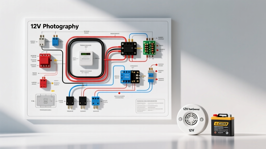
Follow this schematic to properly wire a dual-detector 12V system in a motorhome or sprinter van conversion. Always adhere to SAE J1128 Low Tension Primary Cable standards when selecting wire types.
Phase 1: Power Sourcing and Fuse Selection
- Locate the 12V House Distribution Panel (e.g., Blue Sea Systems or WFCO).
- Install a 2A or 3A ATO/ATC blade fuse in an empty slot. Do not share this circuit with high-draw devices like water pumps or LED lighting arrays, as voltage spikes from inductive loads can fry the detector's logic board.
- Run 16 AWG GXL (Cross-linked polyethylene) wire from the fuse terminal to the first smoke alarm location. GXL wire is required over standard THHN because its thin, abrasion-resistant insulation handles the tight bends and high ambient heat inside RV walls and headliners.
Phase 2: Routing the Interconnect Signal
- Run 18 AWG GXL wire from the interconnect terminal of Alarm 1 to Alarm 2. Because this wire only carries a low-current signal to trigger a high-impedance logic gate in the secondary alarm, 18 AWG is sufficient and saves weight/bulk in the wire loom.
- Secure all wiring runs using Adel clamps (cushioned metal P-clips) bolted to structural framing. Never use plastic zip-ties alone, as UV exposure and thermal cycling will make them brittle, causing the wire harness to drop and chafe against sheet metal.
Phase 3: Grounding and Termination
- Terminate the Black ground wire to a dedicated, star-washed ground bus bar tied directly to the house battery negative terminal.
- Critical Warning: Do not ground the smoke alarm to a random sheet metal screw in the wall cavity. RV skin and framing often have poor continuity due to paint, powder coating, and rubber isolation bushings. A poor ground will cause voltage drops, resulting in the alarm's 'low battery' chirp, even when fully powered.
- Use adhesive-lined marine heat shrink butt connectors (e.g., Ancor brand) for all splices. The internal adhesive melts and seals the wire, preventing copper oxidation caused by condensation inside the vehicle walls.
Wire Color Codes, AWG Sizes, and Termination Specs
Standardizing your wire colors is vital for future troubleshooting and compliance with Recreational Vehicle Industry Association (RVIA) best practices.
| Function | Standard Color | AWG Size | Wire Type | Termination Method |
|---|---|---|---|---|
| Main +12V Power | Red | 16 AWG | GXL / SXL | Insulated Ring Terminal (Fuse) to Spade (Detector) |
| System Ground | Black (or White in older RVs) | 16 AWG | GXL / SXL | Ring Terminal to Ground Busbar with Star Washer |
| Interconnect Signal | Yellow or Orange | 18 AWG | GXL | Adhesive Heat-Shrink Butt Splice |
| Alarm Silence/Mute | Blue (Model Dependent) | 18 AWG | GXL | Momentary Switch to Ground |
Troubleshooting Common 12V Detector Failures
Even with a perfect wiring diagram for smoke alarms, vehicular environments introduce unique electrical gremlins. Use this diagnostic tree to solve common issues:
Symptom 1: Alarm Chirps 'Low Battery' Despite Hardwiring
- Cause A (Voltage Drop): The wire run is too long, or the ground connection has high resistance. The detector requires a minimum of 10.5V at its terminals. Use a digital multimeter (DMM) to measure voltage directly at the alarm's spade connectors while the vehicle's water pump is running. If it drops below 11V, upgrade to 14 AWG wire or clean the ground bus.
- Cause B (Alternator Ripple): A failing alternator diode can introduce excessive AC ripple voltage into the 12V DC system, confusing the detector's microprocessor. Test AC ripple at the battery; it should be under 50mV AC.
Symptom 2: Interconnect Fails to Trigger Secondary Alarm
- Cause: The Yellow interconnect wire is broken, or the signal is being bled off by a faulty secondary detector. Disconnect the interconnect wire at Alarm 2. Trigger Alarm 1 manually (using canned smoke). Probe the disconnected end of the Yellow wire with a DMM. If you read +12V, Alarm 1 is working, and Alarm 2's internal trigger circuit is defective. Replace Alarm 2.
Symptom 3: False Alarms During Cold Starts
- Cause: Condensation and high humidity from breathing in a poorly ventilated camper van can trigger optical smoke sensors. Furthermore, diesel heaters blowing dust across the sensor chamber during initial startup will cause false trips. Relocate the detector away from direct HVAC vents and roof hatches where rain ingress or high humidity occurs.
Final Installation and Testing Protocol
Once the wiring is complete and the 3A fuse is seated, power up the 12V distribution panel. Press the 'Test' button on the primary alarm. Verify that the secondary alarm sounds within 1.5 seconds. Finally, use a can of UL-listed synthetic smoke to test the actual optical/ionization chambers. Document the installation date on the detector housing with a silver paint pen, as RV smoke alarms have a strict 5-to-7-year lifespan due to the degradation of the radioactive isotopes (in ionization models) or the infrared LEDs (in optical models) exposed to vehicular vibration and temperature extremes.