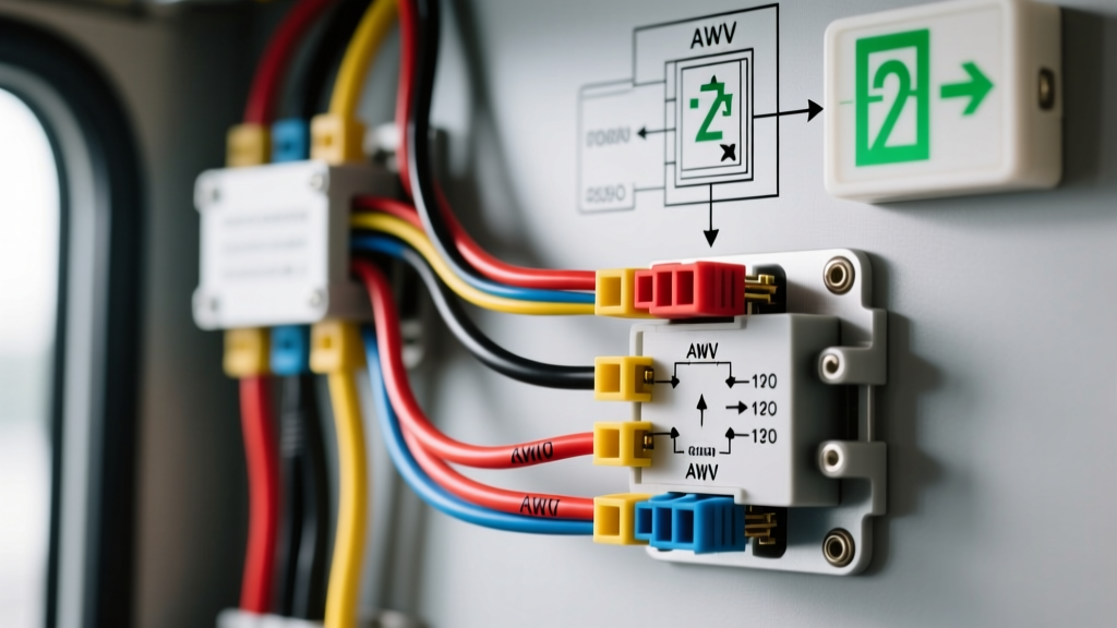
Why 12V DC Exit Signs Are Critical in Custom Vehicles
When converting a school bus (skoolie), Sprinter van, or transit coach into an RV or passenger vehicle, safety codes and common sense dictate the need for clearly marked egress points. While commercial buildings rely on 120V AC or 277V AC hardwired signs, automotive and mobile applications require a specialized approach. Because running a high-wattage inverter solely for emergency lighting is highly inefficient, most mobile builders use 12V or 24V DC LED signs. However, interpreting a standard 12V wiring diagram for exit sign integrations can be confusing for beginners who are used to household AC wiring. This beginner-friendly guide breaks down how to safely wire a low-voltage LED exit sign into your vehicle's house battery system, ensuring your egress lighting is reliable, code-compliant, and protected against the harsh vibrations of the road.
Anatomy of a 12V Wiring Diagram for Exit Sign Circuits
A proper automotive electrical circuit is a closed loop that must be protected from short circuits and voltage spikes. In a mobile environment, the vibration and temperature fluctuations demand higher standards than residential wiring. Your basic 12V DC exit sign circuit consists of five primary components:
- Power Source: Typically the 12V house battery bank (LFP or AGM) via a dedicated busbar.
- Overcurrent Protection: An inline fuse or circuit breaker sized to the wire gauge, not the load.
- Switching Mechanism: A manual toggle switch, a door-actuated micro-switch, or an automotive relay triggered by the ignition or a smart controller.
- The Load: The 12V DC LED exit sign itself.
- Chassis Ground: The return path to the battery negative, utilizing the vehicle's steel frame or a dedicated ground busbar.
Unlike household wiring where neutral and ground are bonded at the panel, automotive DC systems keep the 12V+ positive and the DC ground strictly separated until they meet at the battery terminals or the main inverter/charger busbars.
Component and AWG Specification Chart
Selecting the correct American Wire Gauge (AWG) is critical. Undersized wires in long vehicle runs (like a 40-foot bus) will suffer from severe voltage drop, causing the LED sign to dim or fail to illuminate. According to SAE J1128 standards for low-tension primary automotive cable, you must account for both the amperage draw and the total length of the wire run (positive + negative).
| Wire Gauge (AWG) | Max Continuous Amps | Recommended Fuse Size | Best Application |
|---|---|---|---|
| 16 AWG | 10 Amps | 7.5A or 10A (ATO) | Short runs (<10 ft) for single low-draw LED signs |
| 14 AWG | 15 Amps | 10A or 15A (ATO) | Standard runs (10-20 ft) for multiple LED markers |
| 12 AWG | 20 Amps | 15A or 20A (ATO) | Long runs (20-35 ft) in transit buses and large RVs |
| 10 AWG | 30 Amps | 25A or 30A (ATO/MAXI) | Main feeder lines to a localized lighting distribution block |
Note: Most modern 12V DC LED exit signs draw less than 2 amps. However, we often use 14 AWG or 12 AWG wire to prevent voltage drop over long distances and to provide physical durability against vibration and chafing.
Understanding the Automotive Relay Pinout
If your exit sign needs to be triggered automatically when the vehicle's main power is killed, or if you are switching multiple high-draw egress lights from a single low-amperage smart switch, you must use a standard Bosch-style 4-pin automotive relay. Relays allow a low-current trigger circuit to safely control a high-current load circuit. According to Littelfuse automotive relay specifications, the standard ISO mini relay pinout is universal across most vehicle platforms.
Standard Bosch-Style 4-Pin Relay Configuration
- Pin 30 (Red Wire, 10-12 AWG): Constant 12V+ power directly from the fused battery busbar.
- Pin 87 (Yellow Wire, 14 AWG): Switched 12V+ output leading directly to the positive terminal of the exit sign.
- Pin 85 (Black Wire, 16 AWG): Ground for the relay coil. Connect to a clean chassis ground or ground busbar.
- Pin 86 (Blue Wire, 16 AWG): 12V+ trigger signal. This connects to your manual toggle switch, door jamb plunger switch, or emergency kill-switch controller.
When 12V is applied to Pin 86, the internal electromagnet energizes, pulling the contactor closed between Pin 30 and Pin 87, instantly illuminating the exit sign.
Step-by-Step Installation Guide
Follow these steps to ensure a safe, marine-grade installation that will withstand the rigors of highway travel.
- Tap the Power Source Safely: Never wrap a wire around a battery terminal post. Always use a properly crimped ring terminal connected to a fused distribution busbar (like a Blue Sea Systems ST Blade). Ensure the main busbar fuse is rated for the total load of the panel.
- Install Overcurrent Protection: If you are running a direct line from the battery without a fused busbar, install an inline ATO fuse holder within 7 inches of the positive battery terminal. This protects the wire from catching fire in the event of a dead short against the vehicle chassis.
- Route and Protect the Wiring: Automotive environments are hostile to bare copper. Route your 12V+ and Ground wires through split loom tubing or braided sleeving. Whenever you pass through a metal bulkhead or firewall, you must use a rubber grommet to prevent the sheet metal from slicing through the wire insulation and causing a catastrophic short circuit.
- Make Bulletproof Connections: Avoid cheap crimp connectors. Use adhesive-lined heat shrink ring terminals and spade connectors. The heat-activated glue inside the tubing creates a waterproof seal that prevents corrosion and wicking, which is vital in humid RV environments or exterior bus compartments.
- Establish a True Chassis Ground: The most common cause of 12V lighting failure is a bad ground. Sand away any paint, rust, or undercoating down to bare steel. Use a stainless steel star washer between the ring terminal and the chassis to bite into the metal. Torque the bolt to the manufacturer's specification and coat the terminal with dielectric grease or fluid film to prevent future oxidation.
Troubleshooting Common 12V Egress Lighting Issues
Even with a perfect wiring diagram for exit sign layouts, mobile environments introduce unique electrical gremlins. Here is how to diagnose the most frequent issues:
Symptom: LED Exit Sign Flickers or Strobes
The Cause: Alternator whine and AC ripple voltage. When the vehicle's engine is running, the alternator outputs a rectified AC waveform that isn't perfectly smooth DC. Cheap LED drivers inside the exit sign cannot filter this ripple, resulting in a strobe effect.
The Fix: Solder a 1000µF to 2200µF electrolytic capacitor across the 12V+ and Ground terminals directly at the back of the exit sign. Ensure you observe the correct polarity (negative stripe on the capacitor to the ground wire). This acts as a buffer, smoothing out the alternator ripple and providing steady, flicker-free illumination.
Symptom: Sign is Dim or Will Not Turn On
The Cause: Severe voltage drop due to undersized wire or a high-resistance ground.
The Fix: Use a digital multimeter to test the voltage at the battery (should be ~12.6V resting). Then, probe the 12V+ and Ground wires at the back of the exit sign while the circuit is active. If the voltage reads below 11.5V, you have excessive resistance. Upgrade to a thicker AWG wire, or clean and re-terminate the chassis ground point.
Symptom: Blown Fuses Upon Closing the Door
The Cause: Pinched wires in the door jamb. If your exit sign is wired to a door-actuated micro-switch, the wiring harness passing through the door hinge area is subjected to constant bending.
The Fix: Inspect the door hinge loom for cracked insulation. Replace the damaged section with high-strand-count silicone wire (which is highly flexible) and install a protective rubber door jamb boot to prevent future pinch points.
Final Thoughts on Mobile Safety
Integrating egress lighting into a custom vehicle build is about more than just passing an inspection; it is a critical life-safety system. By treating your 12V DC lighting with the same respect as high-amperage inverter cables—utilizing proper AWG sizing, marine-grade terminations, and relay isolation—you ensure that when the main power fails or an emergency occurs, your exit signs will reliably guide passengers to safety. Always double-check your specific vehicle's chassis grounding points and consult your battery manufacturer's maximum discharge rates before adding continuous loads to your house bank.