The Physics of Coil Saturation and Points Preservation
When automotive electrical systems transitioned from 6-volt to 12-volt architectures in the mid-1950s, engineers faced a critical dilemma regarding ignition coil design. A true 12V ignition coil requires a primary winding resistance of approximately 3.0 to 3.5 ohms to limit current draw to a safe 4 to 5 amps. However, high-resistance coils suffer from slow magnetic saturation times, which limits high-RPM spark output. To solve this, manufacturers utilized low-resistance coils (typically 1.2 to 1.5 ohms primary) designed for 6V or 9V operation, and wired them in series with a ballast resistor. Understanding the 12v ignition coil ballast resistor wiring diagram is essential for restoring classic vehicles, troubleshooting weak spark conditions, and correctly integrating aftermarket electronic ignition modules.
The ballast resistor is a ceramic-housed, wire-wound component that drops the 14.4V alternator charging voltage down to a safe 8V to 9V at the coil positive terminal during normal engine operation. This preserves the life of mechanical breaker points by preventing arcing and burning, and in early electronic systems (like the Chrysler Mopar Orange Box), it prevents the internal power transistor from overheating and failing.
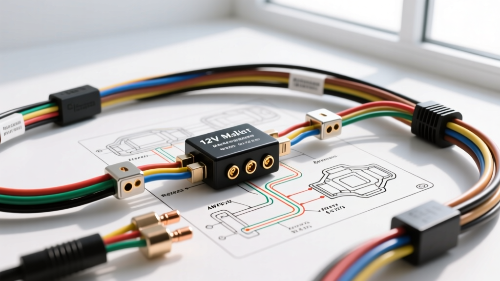
Decoding the 12v Ignition Coil Ballast Resistor Wiring Diagram
A standard ballasted ignition circuit consists of two distinct power feeds to the coil positive terminal: the 'Run' circuit and the 'Start' bypass circuit. Below is the step-by-step electrical trace for a classic V8 application.
1. The 'Run' Circuit (Key in ON Position)
- Battery to Ignition Switch: 12V+ constant power (typically 10 AWG or 12 AWG) feeds the ignition switch battery terminal.
- Ignition Switch to Bulkhead/Firewall: When turned to 'ON', the switch routes power through a 14 AWG wire to the engine bay.
- The Ballast Resistor: The wire enters one terminal of the ballast resistor (typically 1.3 to 1.8 ohms). The resistor dissipates excess voltage as heat, dropping the system voltage from ~14.2V down to ~9.0V.
- Resistor to Coil (+): A 14 AWG wire exits the second terminal of the ballast and connects directly to the positive terminal of the ignition coil.
- Coil (-) to Ground: The negative terminal routes to the mechanical points (condenser and breaker arm) or the electronic ignition control module, which completes the circuit to chassis ground.
2. The 'Start' Bypass Circuit (Key in CRANK Position)
During engine cranking, the starter motor draws 150 to 250 amps, causing a massive voltage drop across the vehicle's electrical system. System voltage at the ignition switch can plummet to 9V or lower. If this 9V passes through the ballast resistor, the coil would receive only 5V to 6V, resulting in a spark too weak to ignite a cold, dense air/fuel mixture. To compensate, the wiring diagram incorporates a bypass circuit.
- Starter Solenoid 'I' Terminal: The starter solenoid (or relay) features an auxiliary terminal labeled 'I' (Ignition) or 'R' (Resistor).
- Bypass Wire Routing: A 16 AWG or 14 AWG wire connects this 'I' terminal directly to the coil positive terminal, completely bypassing the ballast resistor.
- Circuit Logic: When the key is turned to 'START', the solenoid engages. The heavy internal contactor bridges the battery terminal to the starter motor terminal and the 'I' terminal. This feeds raw, unresisted battery voltage (which may be 10.5V during the heavy crank load) directly to the coil, ensuring a hot spark exactly when the engine needs it most.
OEM Wire Color Codes and AWG Specifications
Wire color codes vary significantly by manufacturer. Referencing the correct OEM schematic prevents misdiagnosis and incorrect splicing. According to SAE J1141 standards for automotive wiring systems, maintaining proper AWG sizing is critical to prevent voltage drop and thermal degradation.
| Manufacturer | Circuit Function | Standard Wire Color | AWG Size | Connector Type |
|---|---|---|---|---|
| Chrysler / Mopar | Ignition Switch to Ballast | Brown | 14 AWG | Bulkhead Cavity A/B |
| Chrysler / Mopar | Ballast to Coil (+) | Dark Blue | 14 AWG | Spade / Push-on |
| Chrysler / Mopar | Starter Relay 'I' Bypass | Dark Blue | 16 AWG | Push-on Spade |
| Ford (Pre-1980s) | Ignition Switch to Resistor Wire | Red w/ Green Stripe | 16 AWG (Resistive) | Harness Inline |
| Ford (Pre-1980s) | Starter Solenoid 'I' Bypass | White w/ Blue Stripe | 14 AWG | 10-32 Threaded Stud |
Note: Ford often utilized a specific length of resistive wire (Pink wire) integrated directly into the engine harness rather than a separate ceramic block resistor. This resistive wire typically has 1.5 ohms of resistance per foot.
Diagnostic Decision Tree: Weak Spark vs. No Spark
When troubleshooting a ballasted ignition system using a digital multimeter, as outlined in Fluke automotive diagnostics procedures, follow this voltage-drop sequence to isolate failures.
Step 1: Verify Coil Primary Resistance
Disconnect all wiring from the coil. Set the multimeter to Ohms (Ω). Measure across the (+) and (-) terminals.
Expected: 1.2Ω to 1.5Ω for a ballasted 9V coil. 3.0Ω to 3.5Ω for a true 12V coil.
Fault: If reading near 0Ω, the coil is internally shorted. If reading infinite (OL), the primary winding is open.
Step 2: Test the Ballast Resistor
Disconnect the resistor from the harness. Measure resistance across the two spade terminals.
Expected: 1.2Ω to 1.8Ω.
Fault: Ceramic resistors are prone to cracking and failing open due to extreme thermal cycling. If OL, replace the resistor. Do not bypass it with a standard wire.
Step 3: Dynamic Voltage Testing (Key ON, Engine OFF)
Reconnect all wiring. Back-probe the coil (+) terminal with the multimeter set to DC Volts. Turn the ignition key to 'ON'.
Expected: 7.5V to 9.5V (System voltage minus the ballast drop).
Fault: If reading full 12V+, the ballast resistor is bypassed or shorted (check for previous owner 'fixes'). If reading 0V, check the ignition switch feed and bulkhead connector for corrosion.
Step 4: Dynamic Voltage Testing (Engine CRANKING)
Connect the multimeter to the coil (+) terminal and have an assistant crank the engine.
Expected: Voltage should jump to 10.0V - 12.0V as the starter solenoid 'I' terminal engages the bypass circuit.
Fault: If voltage drops below 7V during cranking, the bypass wire is broken, disconnected from the solenoid, or wired to the wrong terminal (a common mistake is wiring it to the 'S' terminal, which only receives power from the ignition switch, not the battery).
Electronic Ignition Conversion Pitfalls
When upgrading from points to an electronic ignition system (such as Pertronix Ignitor, MSD 6A, or Crane Cams), the ballast resistor wiring diagram must be carefully evaluated. Many modern electronic modules require a full 12V supply to operate their internal Hall-effect sensors and logic boards. However, the coil itself may still require the ballast.
If you are installing an MSD 6A capacitive discharge box, the MSD instructions dictate that the coil (+) terminal must receive full 12V, and the ballast resistor must be bypassed or removed entirely. Conversely, if you are installing a simple points-replacement module (like a Pertronix I) and retaining the stock 1.5-ohm coil, you must retain the ballast resistor in the circuit feeding the coil, or you will melt the coil's internal windings and destroy the module's switching transistor. Always consult the specific module's wiring schematic and verify your coil's primary resistance with a multimeter before applying power. For foundational wiring principles, refer to Automotive Electrical 101 by Kevin R. Sullivan, which details the relationship between circuit resistance, current draw, and thermal limits in 12V DC systems.
Summary of Best Practices
- Never use a 3.0-ohm true 12V coil with a ballast resistor; the resulting voltage drop will yield a severely weak spark.
- Never run a 1.5-ohm ballasted coil on direct 12V without a resistor; the 8+ amp current draw will destroy points, condensers, and electronic modules.
- Always verify the starter solenoid 'I' terminal bypass circuit with a multimeter during cranking to ensure cold-start reliability.
- Use dielectric grease on all bulkhead and spade connectors to prevent moisture-induced voltage drops in the primary ignition feed.