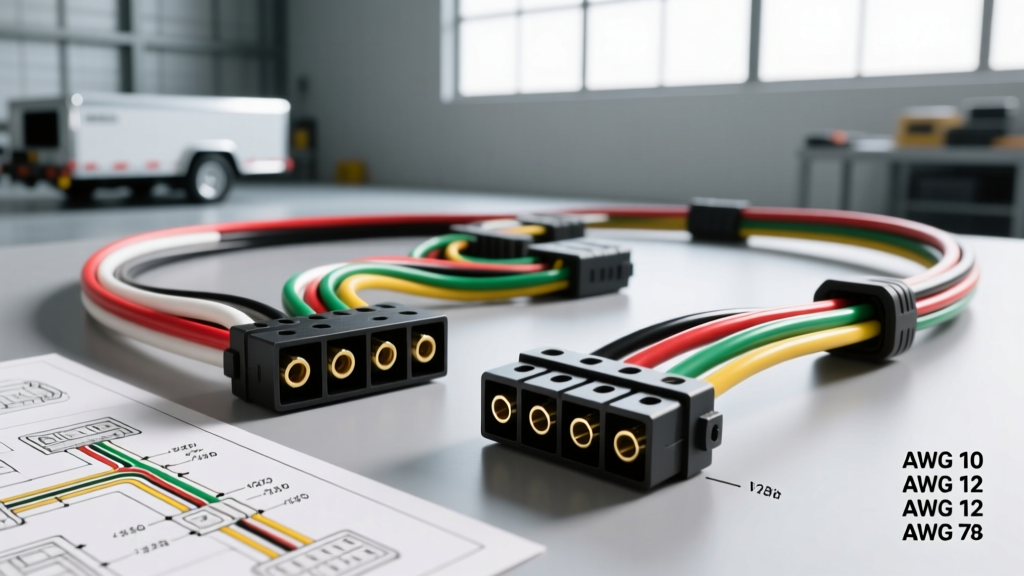
Introduction to Utility Trailer Electrical Systems
Whether you are restoring a rusted 5x10 landscape trailer or building a custom tandem-axle equipment hauler, understanding utility trailer wiring diagrams is the foundation of a reliable lighting and braking system. A poorly executed harness leads to blown fuses, erratic brake controller behavior, and failed DOT inspections. This practical installation guide moves beyond basic color charts, providing the specific AWG requirements, routing techniques, and termination standards required for a professional-grade trailer wiring job.
Decoding Standard Utility Trailer Wiring Diagrams
Most utility trailers rely on either a 4-way flat or a 7-way blade connector. Before cutting any wire, you must identify the pinout standard. The RV Industry Association (RVIA) and SAE International dictate these color codes, though imported or older trailers may feature non-standard wiring. Always test with a digital multimeter before splicing into an existing harness.
The 4-Way Flat Connector (Light Duty)
The 4-pin flat connector is standard for utility trailers under 3,000 lbs GVWR that do not require electric brakes. The wiring diagram consists of four distinct circuits:
- Pin 1 (White): Ground. Must be bonded directly to the trailer frame.
- Pin 2 (Brown): Tail and Running Lights. Runs to all side markers and rear license plate illumination.
- Pin 3 (Yellow): Left Turn Signal and Stop Lamp.
- Pin 4 (Green): Right Turn Signal and Stop Lamp.
The 7-Way Blade Connector (Heavy Duty & Brakes)
For equipment trailers with electric brakes or auxiliary winch power, the 7-way RV blade connector is required. The diagram expands to include high-amperage circuits essential for heavy hauling:
- Pin 1 (White): Main Ground (10 AWG minimum).
- Pin 2 (Brown): Running Lights.
- Pin 3 (Green): Right Turn/Stop.
- Pin 4 (Yellow): Left Turn/Stop.
- Pin 5 (Blue): Electric Brake Output from the tow vehicle's brake controller.
- Pin 6 (Black): 12V Auxiliary Power (for charging breakaway batteries or interior lights).
- Pin 7 (Red/Purple): Reverse Lights or Auxiliary Solenoid (often used for hydraulic surge brake lockout).
Wire Gauge (AWG) and Routing Specifications
Voltage drop is the enemy of trailer lighting, especially when using high-draw incandescent bulbs or running long harnesses on a 20-foot car hauler. Refer to this specification chart to select the correct copper wire gauge (AWG) based on SAE J1128 standards for low-tension automotive primary wire.
| Circuit Function | Recommended AWG | Max Amperage | Insulation Type |
|---|---|---|---|
| Main Ground (White) | 10 AWG | 30A | XLPE / PVC |
| Electric Brakes (Blue) | 12 AWG | 20A | XLPE (High Temp) |
| 12V Aux / Charge (Black) | 10 AWG | 30A | XLPE / PVC |
| Running Lights (Brown) | 16 AWG | 8A | PVC |
| Turn / Stop Lamps (Yellow/Green) | 16 AWG | 10A | PVC |
Step-by-Step Installation Guide
Step 1: Prepare the Frame and Grounding Points
Ninety percent of trailer wiring failures stem from a poor ground. Do not simply screw the white ground wire into a rusty crossmember. Use an angle grinder with a wire wheel to strip the frame down to bare, shiny steel. Drill a 5/16-inch hole, apply a coating of zinc-rich cold galvanizing spray to prevent future rust, and secure a heavy-duty 10 AWG ring terminal using a stainless steel bolt, star washer, and nylock nut. The star washer bites through the metal to ensure a zero-resistance electrical path.
Step 2: Route and Protect the Main Harness
Never zip-tie wires directly to sharp steel edges or suspend them near the axle where road debris can strike. Route the main harness through the interior channel of the C-channel or box-tube frame rails. Where the harness must drop down to the axle for electric brake connections, use split loom tubing and secure it with adhesive-lined stainless steel P-clamps. Leave a service loop of at least 12 inches near the tongue jack to allow for articulation without putting tension on the trailer plug.
Step 3: Splice, Solder, and Seal
Twist connectors and electrical tape are unacceptable for exterior trailer environments. Moisture will wick into the copper strands via capillary action, causing green corrosion and open circuits within months. For all splices, strip the wire, twist the copper strands, and solder the joint using rosin-core solder. Once cooled, slide a piece of dual-wall, adhesive-lined marine heat shrink over the joint and apply heat until the inner sealant melts and oozes from the ends. This creates a completely waterproof, strain-relieved connection.
Step 4: Integrating the Breakaway Switch
Any utility trailer equipped with electric brakes legally requires a breakaway switch. Wire the breakaway switch pin directly to the positive terminal of the dedicated breakaway battery, and connect the switch's output wire to the blue electric brake wire downstream of the 7-way plug. Never wire the breakaway switch through the trailer's main ground or lighting circuits; it must deliver full battery voltage directly to the brake magnets in the event of a detachment.
Upgrading from 4-Pin to 7-Pin Configurations
If your utility trailer requires the addition of electric brakes, you must upgrade the harness. You can use a 4-to-7-way adapter plug for temporary use, but a hardwired junction box is the professional standard. Mount a weatherproof trailer junction box near the tongue. Run a new 7-way molded pigtail into the box, and connect your existing 4-way lighting circuits alongside the new 12 AWG blue brake wire and 10 AWG black auxiliary wire. Use ring terminals for all junction box connections to prevent vibration-induced loosening.
Troubleshooting Common Voltage Drop and Ground Issues
Symptom: Turn signal blinks rapidly on the dash, but trailer lights do not flash.
Cause: Insufficient ground path or high resistance in the turn signal circuit.
Fix: Check the white ground wire at the frame. Clean the contact point. If using LED trailer lights, ensure the tow vehicle has a PWM (Pulse Width Modulation) compatible flasher relay, as older thermal flashers rely on the high amperage draw of incandescent bulbs to cycle.
Symptom: Running lights illuminate, but pressing the brake pedal causes them to dim or turn off.
Cause: Backfeeding due to a missing or corroded ground at the trailer tongue. The brake circuit is seeking a ground path backward through the running light circuit.
Fix: Isolate the ground wire from the lighting circuits. Ensure each individual light fixture has its own dedicated ground wire tied to the main harness ground, or that the fixture base is grounded to a perfectly clean metal surface.
Symptom: Electric brake controller displays an "SH" (Short) or "OL" (Overload) error code when stepping on the brake pedal.
Cause: A short to ground in the blue brake wire, often caused by chafing against the trailer axle or a burnt-out brake magnet coil.
Fix: Disconnect the blue wire at the junction box and use a multimeter to test continuity between the blue wire and the trailer frame. Inspect the wire routing near the axle U-bolts and the backing plates where the magnets are housed. Replace any melted or pinched wiring and seal with liquid electrical tape.
Authoritative References
For comprehensive legal requirements regarding commercial and heavy-duty trailer lighting, refer to the Federal Motor Carrier Safety Administration (FMCSA) Section 393.9, which outlines mandatory lighting devices and reflectors. For standardized electrical connector pinouts and jumper cable specifications, consult the SAE J560 Standard for seven-conductor connectors. Additionally, the RV Industry Association (RVIA) provides extensive guidelines on low-voltage DC wiring practices applicable to enclosed and utility trailers.