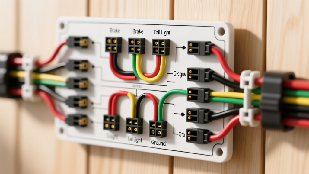
Introduction to 7-Way RV Blade Connector Diagnostics
When dealing with complex towing setups, referencing an accurate 7 pin wiring diagram for trailers is only the first step in ensuring a safe and legal tow. The standard 7-way RV blade connector is the backbone of modern heavy-duty towing, managing everything from basic illumination to high-amperage electric brake circuits and 12V auxiliary charging. However, because this connector is exposed to extreme environmental conditions—including road salt, water immersion, and constant vibration—electrical faults are incredibly common.
As an automotive electrical specialist, I frequently see towers misdiagnose trailer wiring issues by replacing perfectly good brake controllers or tail lights, only to find the root cause was a degraded ground circuit or a PWM signal mismatch. This guide provides a rigorous, step-by-step troubleshooting flow designed to isolate faults in your 7 pin wiring diagram for trailers using systematic voltage and continuity testing.
Standard 7 Pin Wiring Diagram for Trailers: Reference Specifications
Before connecting your digital multimeter (DMM), verify that your trailer harness adheres to the RVIA (Recreation Vehicle Industry Association) standard color codes. Deviating from these standards is the leading cause of cross-wired circuits and blown vehicle fuses.
| Circuit Function | Standard Wire Color | Minimum AWG Rating | Circuit Characteristics |
|---|---|---|---|
| System Ground | White | 10 AWG (8 AWG preferred) | Common return path for all lighting and brake circuits. |
| Electric Brake Output | Blue | 10 AWG | Carries PWM or variable DC voltage (0-12V) from the brake controller. |
| 12V Auxiliary / Charge | Black (or Red) | 10 AWG | Constant 12V+ for breakaway battery charging or interior lights. |
| Tail / Running / Marker | Brown | 14 AWG | Switched 12V+ from vehicle headlight circuit. |
| Left Turn / Stop | Yellow | 14 AWG | Switched 12V+ pulsed or constant depending on vehicle logic. |
| Right Turn / Stop | Green | 14 AWG | Switched 12V+ pulsed or constant depending on vehicle logic. |
| Reverse Lights / Aux | Purple | 14 AWG | Switched 12V+ tied to vehicle reverse lamp circuit. |
Phase 1: Visual and Physical Connection Inspection
Never skip the physical inspection. Over 60% of 7-way connector faults are mechanical or environmental, not electrical.
- Pin Tension and Spread: Inspect the female socket on the tow vehicle. The brass contacts frequently spread apart over time, causing intermittent arcing when hitting bumps. Use a small pick tool to gently bend the contacts inward to ensure a tight grip on the male trailer plug.
- Galvanic Corrosion: Look for green or white crusty buildup. This occurs when dissimilar metals (brass pins and copper wire) react in the presence of moisture. Clean with electrical contact cleaner and a brass wire brush.
- Dielectric Grease Application: After cleaning, pack the female socket with a silicone-based dielectric grease. Warning: Do not use standard chassis grease or WD-40, as these can degrade the rubber weather seals and attract conductive road dust.
- Wire Strain Relief: Check the back of the plug where the wires enter the housing. If the outer jacket is pulled back, exposing the individual colored wires to moisture, the internal crimps will inevitably corrode and fail.
Phase 2: Multimeter Voltage and Continuity Decision Tree
Set your DMM to DC Voltage for live circuit testing, and Ohms/Continuity for dead circuit testing. Follow this decision tree based on your primary symptom.
Symptom A: Electric Brakes Lock Up or Fail to Engage
The blue wire circuit is highly sensitive to voltage drop and signal type. Modern proportional brake controllers (like the Tekonsha Prodigy P3 or Redarc Tow-Pro) output a Pulse Width Modulated (PWM) signal rather than a steady DC voltage.
- Step 1: Connect your DMM to the Blue pin on the vehicle socket (grounded to the White pin). Have an assistant apply the manual override slider on the brake controller.
- Step 2: Observe the voltage. If you see erratic jumping (e.g., 2V to 11V rapidly) instead of a steady 12V, this is normal for PWM controllers. Use a dedicated trailer circuit tester or an analog test light to verify the signal is reaching the plug.
- Step 3: If the brakes lock up immediately upon plugging in, check for a short between the Blue (Brake) and Black (12V Aux) wires. This is common in trailer junction boxes where moisture causes a bridge between adjacent screw terminals.
- Step 4: If brakes are weak, perform a voltage drop test on the trailer side. Measure voltage between the Blue wire at the brake magnet and the trailer frame. A reading above 0.5V under load indicates high resistance in the ground return path, not a bad brake controller.
Symptom B: Erratic Turn Signals and Brake Lights
This is almost always caused by LED backfeeding or a compromised ground.
- Step 1: Verify the White ground wire. Many towers mistakenly rely on the hitch ball for the ground return. The hitch ball is painted, greased, and subject to articulation. The dedicated 10 AWG White wire must be bolted directly to the trailer frame using a star washer and torqued to 10-15 ft-lbs.
- Step 2: Check for LED backfeed. If your trailer uses LED clearance lights but incandescent turn signals, the lower resistance of the LEDs can cause current to backfeed through the Brown (Tail) circuit into the Yellow/Green circuits. This causes turn signals to hyper-flash or stay on dimly. Install inline isolating diodes on the tail light circuit to prevent this.
- Step 3: Test the vehicle-side flasher relay. Modern vehicles use solid-state flasher modules that detect wattage. If you swapped all trailer lights to LEDs without adding load resistors, the vehicle module will think a bulb is out and hyper-flash the turn signals.
Symptom C: Running Lights Fail When Headlights Engage
- Step 1: Measure voltage at the Brown pin on the vehicle socket with the headlights ON. You should read 12.0V to 12.6V.
- Step 2: If voltage is present at the vehicle but lights don't turn on, the fault is on the trailer. Trace the Brown wire to the trailer junction box.
- Step 3: Check for 'phantom grounds'. If the Brown wire insulation is chafed against the metal trailer frame, the current will ground out before reaching the tail lights, often blowing the vehicle's tow package fuse (usually a 30A or 40A fuse in the under-hood PDC).
Phase 3: Advanced Ground and Voltage Drop Testing
The most misunderstood aspect of any 7 pin wiring diagram for trailers is the ground circuit. The White wire is not just a formality; it carries the return amperage for every single circuit on the trailer. If you are running four marker lights, two tail lights, and charging a breakaway battery, the White wire can easily carry 15+ amps.
The Voltage Drop Test Procedure:
- Turn on all trailer running lights and apply the manual brake override to place the system under maximum load.
- Set your DMM to DC Volts.
- Place the RED probe on the negative terminal of the tow vehicle's battery.
- Place the BLACK probe on a clean, bare metal spot on the trailer frame (near the axles).
- Read the voltage. A reading of 0.00V to 0.2V indicates a healthy ground path. A reading of 0.5V or higher means the White wire is undersized, corroded, or the frame grounding point is compromised by rust or paint.
Expert Fix: If voltage drop is high, do not simply replace the White wire with another 12 AWG wire. Upgrade the main ground harness to 8 AWG flexible copper welding cable, and add secondary ground straps between the trailer tongue and the suspension axles to ensure the brake magnets have a flawless return path.
Common Failure Modes in 7-Way Harnesses
- Junction Box Moisture Intrusion: Many trailers use a plastic junction box at the tongue to transition from the 7-way plug to the split harness. The rubber gaskets on these boxes dry rot within 3-5 years. Water enters, pools at the bottom, and corrodes the ring terminals. Seal the lid with black RTV silicone.
- Breakaway Switch Drain: The Black (12V Aux) wire is often tied to a breakaway battery. If the vehicle's alternator is not outputting enough voltage to overcome the trailer's parasitic draw, the vehicle will actually charge the trailer battery backwards, or the trailer battery will drain the vehicle battery when parked. Install a 40A auto-reset circuit breaker and a heavy-duty isolation solenoid on the Black wire circuit.
- Blade Connector Pin Fatigue: The male pins on the trailer plug are stamped steel with a brass plating. Over time, the plating wears off, exposing the steel to rapid oxidation. If your plug pins are pitted or dull, replace the entire plug head. Do not attempt to sand them, as this removes the remaining corrosion-resistant plating.
Authoritative References and Standards
For further technical specifications regarding trailer lighting and braking circuits, consult the following industry standards and expert resources:
- SAE J286 - Lighting and Electrical Standards: The Society of Automotive Engineers baseline for vehicular lighting circuits and color coding.
- Recreation Vehicle Industry Association (RVIA): Governing body for standard RV and travel trailer 7-way blade pinouts and manufacturing safety codes.
- etrailer.com Wiring FAQ and Troubleshooting Guides: Comprehensive field-tested data on PWM brake controller compatibility and LED trailer light conversion resistors.