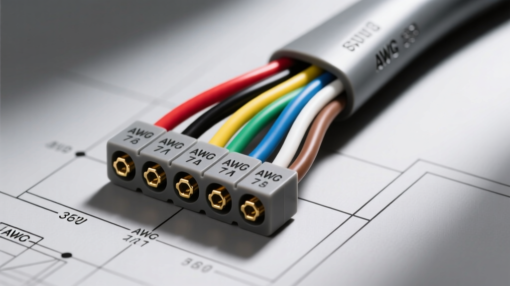
Understanding the 7-Pin Round Connector Standard
The 7 pin round wiring diagram is a critical reference for fabricators, agricultural equipment operators, and heavy-duty commercial fleets. Unlike the ubiquitous 7-way RV blade connector standardized by the RV Industry Association (RVIA), the 7-pin circular connector relies on robust, threaded or smooth cylindrical pins designed to withstand high-vibration environments, mud, and extreme weather. Often referred to as the commercial or agricultural 7-way, this connector is heavily utilized in farming, construction, and heavy-equipment towing where standard plastic blade connectors would quickly fail due to mechanical stress or environmental ingress.
When referencing a 7 pin round wiring diagram, it is vital to distinguish it from the 7-way RV blade. While the electrical functions (ground, tail, left turn, right turn, brakes, 12V aux, reverse) remain largely consistent across North American towing standards, the physical pin layout, terminal types, and wire gauge requirements for heavy-duty round connectors demand a more rigorous approach to assembly and maintenance. According to SAE International standard J286 and related heavy-duty specifications, circular connectors must maintain strict environmental sealing and current-carrying capacities to ensure safe operation of electric brakes and lighting systems under maximum load.
Standard 7-Pin Round Pinout and Color Code Reference
The standard North American 7-pin round connector utilizes a specific clock-face or numbered pin layout. When looking at the face of the trailer-side plug (the male pins), the configuration is as follows:
| Pin Number | Function | Standard Wire Color | Minimum AWG | Max Amperage |
|---|---|---|---|---|
| Pin 1 | Ground (Chassis) | White | 10 AWG | 40A |
| Pin 2 | Tail / Running Lights | Brown | 14 AWG | 15A |
| Pin 3 | Left Turn / Stop | Yellow | 12 AWG | 20A |
| Pin 4 | Right Turn / Stop | Green | 12 AWG | 20A |
| Pin 5 | Electric Brakes | Blue | 10 AWG | 30A |
| Pin 6 | Auxiliary / 12V Power | Black or Red | 10 AWG | 30A |
| Pin 7 | Reverse Lights / Backup | Purple | 14 AWG | 15A |
Pin 1 (Ground): The white wire is the most critical circuit in the 7 pin round wiring diagram. It must be bonded directly to the trailer chassis using a star washer and a bare-metal contact point. Never rely solely on the hitch ball for grounding, as paint, rust, and grease will create high-resistance paths.
Pin 5 (Electric Brakes): The blue wire carries the pulsing DC voltage from the tow vehicle's brake controller. Because electric brake magnets can draw up to 6 amps per wheel (24 amps total on a quad-brake trailer), undersizing this wire will result in severe voltage drop and weak braking performance.
Pin 6 (Auxiliary 12V): Typically black or red, this pin provides constant 12V power for charging trailer breakaway batteries, operating interior lights, or powering hydraulic dump trailer pumps. If used for a hydraulic pump, a dedicated 40A circuit breaker should be installed within 18 inches of the tow vehicle's battery.
Wire Gauge (AWG) and Voltage Drop Calculations
A common mistake when building heavy-duty trailers is using standard 16 AWG automotive wire for all circuits. While 16 AWG may suffice for LED marker lights, it is entirely inadequate for the electric brake and ground circuits on a 25-foot gooseneck or equipment trailer.
Voltage drop is calculated using the formula: Voltage Drop = (2 x Length x Current x Resistance per foot). For a 25-foot trailer (50 feet total round-trip wire length) drawing 20 amps on the electric brake circuit (Pin 5), using 12 AWG wire (which has a resistance of roughly 0.001588 ohms per foot) results in a voltage drop of approximately 3.17 volts. This means your brake magnets are only receiving 8.8 volts instead of the required 12 volts, reducing braking torque by over 25%. By upgrading to 10 AWG wire for the brake and ground circuits, the resistance drops, ensuring maximum braking efficiency and preventing the wire from overheating inside the conduit.
For comprehensive wire sizing charts and ampacity ratings, fabricators should consult the etrailer.com wiring FAQ and AWG specification guides, which align with SAE J1128 standards for low-tension automotive primary cable.
Terminal Types: Solder Cup vs. Screw Terminal
Heavy-duty 7-pin round connectors typically come in two termination styles: solder cup and screw terminal. Each requires a specific assembly technique to prevent failure in high-vibration environments.
Solder Cup Terminals
Solder cups feature a small cylindrical well at the base of each pin. To terminate, the wire is stripped, twisted, inserted into the cup, and flooded with 60/40 rosin-core solder. Expert Tip: Use a high-wattage soldering iron (minimum 60W) or a butane soldering torch. A low-wattage iron will take too long to heat the heavy brass pin, causing the heat to travel up the pin and melt the plastic or rubber connector body insert, ruining the connector. Always apply marine-grade adhesive-lined heat shrink over the solder joint to prevent moisture wicking.
Screw Terminal Connectors
Screw terminal 7-pin round connectors are preferred for field repairs and heavy agricultural use because they do not require soldering. However, simply wrapping a stranded wire around a screw is a violation of electrical best practices and will lead to strand fraying and short circuits. You must use crimped wire ferrules or tinned wire ends. The terminal screws should be torqued to exactly 5 to 7 inch-pounds. Over-torquing will strip the brass threads or cut through the copper strands, while under-torquing will allow vibration to loosen the connection, resulting in arcing and melted plastic housings.
Environmental Sealing and Corrosion Prevention
The circular design of the 7-pin connector is inherently better at shedding water than flat blade connectors, but the internal pin cavity is still vulnerable to capillary action and galvanic corrosion. Before mating the plug and socket, apply a liberal amount of dielectric grease (such as Permatex or Noalox) to the pins. This displaces moisture and prevents the formation of copper oxide, which acts as an insulator and causes voltage drop.
For the rear of the connector where the wires enter the housing, use a two-part epoxy putty or a heavy-duty rubber strain relief boot filled with silicone sealant. This prevents water from traveling down the wire jacket and into the solder cups—a phenomenon known as 'wet stringing' that frequently destroys trailer wiring harnesses from the inside out.
Diagnostic Troubleshooting: Real-World Failure Modes
When a trailer electrical system fails, the 7 pin round wiring diagram serves as your diagnostic map. Below are three common failure modes specific to heavy-duty round connectors and how to diagnose them using a Digital Multimeter (DMM).
Scenario A: Electric Brakes Lock Up When Headlights Are Turned On
Cause: This is a classic 'ground loop' or 'backfeed' issue. If the ground circuit (Pin 1) has high resistance due to corrosion or a poor chassis bond, the current from the tail lights (Pin 2) will seek an alternative path to ground. It backfeeds through the electric brake circuit (Pin 5), energizing the brake magnets whenever the running lights are on.
Fix: Disconnect the trailer. Set your DMM to continuity mode. Test between Pin 1 on the trailer plug and a clean, bare-metal spot on the trailer frame. If resistance is above 0.5 ohms, clean the ground stud, replace the ring terminal, and apply anti-corrosion compound.
Scenario B: Brake Controller Displays 'S.H.' (Short Circuit) Immediately
Cause: A direct short between the brake output (Pin 5) and ground (Pin 1). In 7-pin round connectors, this is almost always caused by moisture ingress inside a poorly sealed solder cup, creating a conductive bridge between the adjacent pins, or a melted wire insulation inside the trailer's A-frame conduit.
Fix: Unplug the trailer. Use the DMM to check for continuity between Pin 5 and Pin 1 on the trailer side. If it reads near zero ohms, open the connector housing and inspect the solder joints. If the joints are dry, inspect the wiring where it bends at the trailer tongue, as flex fatigue often causes the blue and white wires to short together.
Scenario C: Phantom Voltage on Auxiliary Pin (Pin 6)
Cause: You measure 3 to 5 volts on Pin 6 with a high-impedance DMM, even when the tow vehicle is off and the circuit should be dead. This is 'phantom voltage' caused by capacitive coupling between the long, parallel wire runs inside the trailer harness, or a failing solid-state relay in the tow vehicle's isolation module.
Fix: Place a 10-ohm, 10-watt dummy load resistor across Pin 6 and Pin 1. If the voltage immediately drops to zero, it is harmless phantom voltage. If it remains, you have a faulty isolation relay or a shorted diode in the tow vehicle's converter box.
Authoritative References and Further Reading
For engineers and fleet mechanics requiring exhaustive specifications on heavy-duty trailer connectors, the following resources are highly recommended:
- SAE International: Refer to SAE J286 for truck-trailer connector dimensions and performance requirements, and SAE J560 for heavy-duty 7-way electrical systems.
- TE Connectivity / Pollak: Consult the Pollak Heavy-Duty Connector Catalog for precise torque specifications, pin extraction tools, and environmental IP-rating data for circular commercial connectors.
- NEC / NFPA 70: While primarily for residential/commercial buildings, Article 551 of the National Electrical Code provides foundational guidelines for low-voltage DC grounding and overcurrent protection in recreational and mobile applications.
By strictly adhering to the 7 pin round wiring diagram, utilizing the correct AWG wire sizes, and employing military-grade termination techniques, you ensure that your heavy-duty trailer will maintain flawless electrical operation across thousands of miles of punishing terrain.