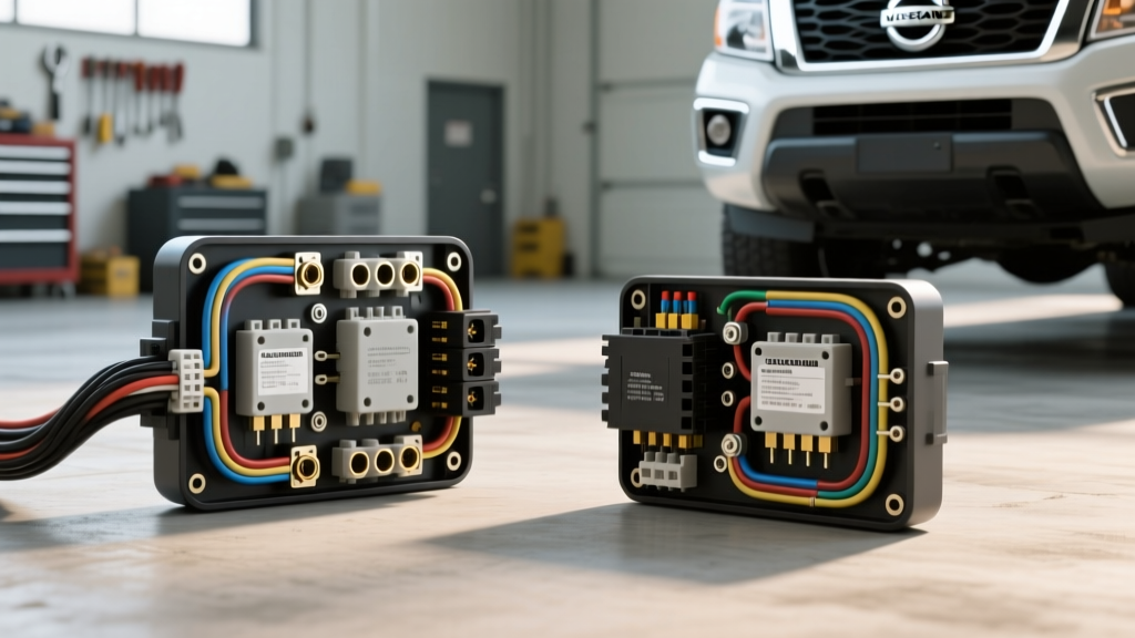
The D41 Platform: Multiplex Networks and Towing Safety
The 2025 Nissan Frontier (continuing the robust D41 generation) features a highly sophisticated electrical architecture managed by a centralized Body Control Module (BCM) and an Intelligent Power Distribution Module (IPDM). When installing or troubleshooting a 2025 Nissan Frontier trailer wiring harness, treating the truck like an older, analog 12-volt system is a recipe for catastrophic electrical failure. The Frontier utilizes multiplex communication networks and Pulse Width Modulation (PWM) for its exterior LED lighting. This means the wiring harness must be specifically designed to interpret digital signals rather than simply tapping into raw 12V analog feeds. Ignoring these platform-specific nuances is the leading cause of blown BCM fuses, hyper-flashing trailer lights, and in severe cases, under-dash electrical fires.
Critical Warning: PWM Taillights and Aftermarket T-Harnesses
If your 2025 Frontier did not leave the factory with the official Tow Package, you will likely be installing an aftermarket T-connector harness (such as those from Curt or Tekonsha) behind the rear bumper or taillight assemblies. The most dangerous mistake DIYers make is using "scotch-lock" or "vampire" taps directly into the Frontier’s rear lighting wires. The Frontier’s BCM uses PWM to dim the LEDs for running lights and pulses full voltage for brake lights. A standard, unpowered trailer converter will misread this duty cycle, resulting in trailer running lights that flicker violently or fail to illuminate entirely. You must use a powered converter module that draws its heavy amperage directly from the battery via a dedicated 12V feed, using the Frontier’s taillight wires only as low-amperage signal triggers.
2025 Frontier 7-Pin SAE J286 Pinout & Wire Gauge Matrix
Whether you are utilizing the factory-installed 7-way RV blade receptacle or upgrading a 4-pin flat connector, adherence to the SAE J286 Standard is mandatory for safety and interoperability. Below is the required wire gauge and pinout matrix for a fully functional 7-pin setup on the 2025 Frontier.
| Pin | Function | Standard Wire Color | Minimum AWG | Circuit Breaker / Fuse |
|---|---|---|---|---|
| 1 | Left Turn / Stop | Yellow | 14 AWG | BCM Protected (10A) |
| 2 | Electric Brakes | Blue | 10 AWG | 30A Auto-Reset |
| 3 | Ground (Chassis) | White | 10 AWG | N/A |
| 4 | 12V Aux / Battery Charge | Red / Black | 10 AWG | 30A Inline |
| 5 | Right Turn / Stop | Green | 14 AWG | BCM Protected (10A) |
| 6 | Tail / Running Lights | Brown | 14 AWG | 15A (IPDM) |
| 7 | Reverse / Backup Aux | Black / Purple | 14 AWG | 15A Inline |
Top 4 Harness Installation Mistakes That Cause Meltdowns
Mistake 1: Bypassing the IPDM Relays for 12V and Brake Power
On 2025 Frontier models equipped with the factory tow package but lacking an integrated brake controller, the under-hood wiring is often "present but dormant." A massive safety oversight occurs when installers run the blue electric brake wire or the red 12V auxiliary wire directly from the battery to the 7-pin plug without installing the required 30A relays in the IPDM (located in the engine bay near the passenger-side firewall). Without these relays acting as a physical isolation barrier, a short circuit at the trailer plug can backfeed voltage directly into the Frontier’s BCM, instantly frying a module that costs upwards of $1,200 to replace and reprogram. Always verify relay presence in the IPDM box before applying power to Pin 2 and Pin 4.
Mistake 2: Relying on the Hitch Ball for a Ground Path
Pin 3 (White) is the most critical circuit on your trailer. Many installers assume the physical connection between the trailer coupler and the Frontier’s hitch ball provides an adequate ground. This is a severe safety hazard. The hitch ball is painted, often coated in grease, and subject to dynamic articulation that breaks electrical continuity. A poor ground forces the trailer's lighting circuits to seek alternative ground paths through the turn signal filaments, causing the "strobing" effect where brake lights flash when the turn signals are engaged. The Fix: Run a dedicated 10 AWG white wire from the 7-pin plug directly to a bare, sanded metal surface on the Frontier’s chassis frame rail. Secure it with an M8 flange bolt, a star washer to bite through any surface rust, and torque it to 15 ft-lbs. Coat the terminal in marine-grade grease to prevent galvanic corrosion.
Mistake 3: Splicing Directly into the CAN Bus
The 2025 Frontier’s rear lighting harness is integrated into the vehicle's CAN (Controller Area Network) bus. If an installer accidentally taps into a CAN-high or CAN-low communication wire instead of the dedicated 12V lighting feed, the resulting voltage spike will trigger a BCM thermal shutdown. The truck will throw a "Lighting System Malfunction" code on the dash, and the taillights will remain completely dead until the code is cleared with an advanced bi-directional OBDII scanner. Always use a digital multimeter to verify a steady 12V DC reading on the suspected lighting wire before making any connections.
Mistake 4: Ignoring Dielectric Seals on the Bumper Receptacle
The Frontier’s rear bumper is highly exposed to road spray, salt, and debris. Failing to pack the rear of the 7-pin receptacle and the trailer plug with silicone dielectric grease invites moisture ingress. Over a single winter, this causes galvanic corrosion between the copper wire strands and the brass connector pins. This corrosion increases electrical resistance, which generates extreme heat under heavy amperage loads (like charging a trailer breakaway battery or powering interior trailer lights), eventually melting the plastic housing of the connector.
Under-Hood Brake Controller Integration
The 2025 Frontier does not feature a factory-integrated trailer brake controller on the dash like some heavy-duty competitors. Owners must install an aftermarket unit (such as the Tekonsha Prodigy P3 or Redarc Tow-Pro Elite). The Frontier features a dedicated blunt-cut pigtail or a proprietary plug located under the driver’s side dash, typically zip-tied near the OBDII diagnostic port or behind the left kick panel. According to Tekonsha Technical Bulletins, you must ensure the heavy 12V power wire for the brake controller is fused within 18 inches of the battery positive terminal. If the factory pigtail is missing the heavy red power wire, you must run a new 10 AWG wire through the firewall grommet, utilizing a 30A auto-reset circuit breaker to protect the controller from voltage spikes during trailer disconnects.
Pre-Tow Multimeter Diagnostic Checklist
Before hooking up your trailer and hitting the highway, perform this mandatory safety checklist using a digital multimeter set to DC Voltage (20V scale):
- Pin 3 to Pin 6 (Ground to Tail): Should read exactly 12.4V - 12.6V with the Frontier's headlights ON. Anything below 11.5V indicates excessive resistance in the ground wire.
- Pin 4 to Pin 3 (12V Aux to Ground): Should read battery voltage. If it reads 0V, check the under-hood IPDM relay and the 30A inline fuse near the battery.
- Pin 2 to Pin 3 (Brakes to Ground): Should read 0V at rest. Have a helper press the manual override lever on your aftermarket brake controller; voltage should smoothly ramp from 0V to 12V.
- PWM Signal Verification: Probe the brown running light wire at the converter box. If you see a rapidly pulsing voltage rather than a steady 12V, your converter module is failing to filter the Frontier's PWM signal and must be replaced with a powered, PWM-compatible module.
Authoritative References
For comprehensive towing capacities, payload limits, and factory hitch receiver torque specifications, always consult the official Nissan USA Towing Guide and your specific 2025 Frontier Owner’s Manual. Ensuring your wiring harness is rated for the Gross Combined Weight Rating (GCWR) of your specific Frontier trim (e.g., SV vs. Pro-4X) is the final step in guaranteeing a safe, legally compliant tow setup.