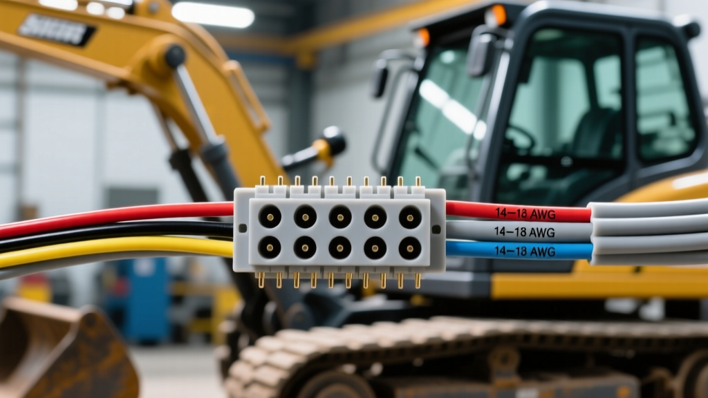
Introduction to Skid Steer 14-Pin Electrical Systems
If you are stepping into the world of heavy mobile equipment and advanced hydraulics, understanding the 14 pin connector for skid steer wiring diagram is an essential first step. While standard trailer wiring relies on simple 4-pin or 7-pin configurations for basic lighting, modern skid steers and compact track loaders (CTLs) utilize a robust 14-pin interface to communicate with complex attachments. These attachments include cold planers, trenchers, sweepers, and tilt rotators that require both high-amperage power and sophisticated digital communication.
For beginners, the jump from simple analog switches to digital attachment control can seem intimidating. However, by breaking down the wiring diagram into its core circuits—power, ground, control signals, and data networks—you can confidently troubleshoot, repair, and maintain your equipment. This guide provides a beginner-friendly yet technically rigorous breakdown of the industry-standard 14-pin layout, heavily based on the ubiquitous Bobcat Attachment Control Device (ACD) architecture.
The Evolution: Why 14 Pins?
Older skid steers utilized a simple 7-pin connector. This older standard provided basic 12-volt power, ground, and a few discrete analog circuits to trigger hydraulic solenoids. While sufficient for basic buckets and grapples, the 7-pin system lacked the bandwidth required for modern attachments featuring electronic control units (ECUs), joystick proportionality, and diagnostic feedback.
The 14-pin connector was introduced to solve these limitations. It separates high-current power delivery from sensitive data lines, incorporates Pulse Width Modulation (PWM) capabilities for proportional hydraulic control, and integrates a Controller Area Network (CAN) bus. This allows the skid steer’s main computer to recognize the attachment, adjust hydraulic flow rates automatically, and display diagnostic codes on the operator’s dashboard.
Standard 14-Pin Skid Steer Wiring Diagram & Pinout Table
The physical 14-pin connector typically uses heavy-duty, environmentally sealed circular housings, such as the TE Connectivity Deutsch DT Series or equivalent Amphenol designs. The pins are lettered rather than numbered to prevent confusion during field repairs. Note that the letters "I" and "O" are intentionally skipped in the standard sequence to avoid misreading them as the numbers "1" and "0".
| Pin Letter | Primary Function | Standard Wire Color | Recommended AWG | Circuit Type |
|---|---|---|---|---|
| A | Switched 12V Power | Red | 10 AWG | High-Current Power |
| B | Chassis Ground | Black | 10 AWG | High-Current Ground |
| C | CAN High (Data +) | Orange | 18 AWG | Digital Data Network |
| D | CAN Low (Data -) | Yellow | 18 AWG | Digital Data Network |
| E | Auxiliary Control 1 (PWM/12V) | Blue | 14 AWG | Solenoid Trigger |
| F | Auxiliary Control 2 (PWM/12V) | Green | 14 AWG | Solenoid Trigger |
| G | Auxiliary Control 3 | White | 14 AWG | Solenoid Trigger |
| H | Auxiliary Control 4 | Brown | 14 AWG | Solenoid Trigger |
| J | Enable / E-Stop Override | Purple | 16 AWG | Safety Logic |
| K | Case Drain / Feedback | Gray | 14 AWG | Sensor / Return |
| L, M, N, P | Reserved / OEM Specific | Various | 16-18 AWG | Future Expansion |
Note: Always consult your specific machine’s Bobcat Attachment Manuals or OEM service documentation, as aftermarket attachment manufacturers may repurpose reserved pins for proprietary sensors.
Deep Dive: The CAN Bus Circuit (Pins C & D)
The most critical difference between a standard trailer wiring harness and a skid steer attachment harness is the inclusion of a Controller Area Network (CAN) bus. Operating under the SAE J1939 Standard for heavy-duty vehicles, the CAN bus allows the skid steer’s main ECU and the attachment’s ECU to share data without requiring a dedicated wire for every single sensor.
How the Twisted Pair Works
Pins C (CAN High) and D (CAN Low) must be wired using a twisted pair of 18 AWG wires. Twisting the wires cancels out electromagnetic interference (EMI) generated by the skid steer’s alternator, ignition system, and high-amperage hydraulic solenoids. If you are repairing a broken CAN line, never untwist the wires more than an inch from the termination point, or you will introduce signal noise that causes the attachment to drop offline.
Termination Resistors
A healthy CAN bus circuit requires exactly two 120-ohm termination resistors—one located inside the skid steer’s main harness, and one located inside the attachment’s ECU. These resistors prevent data signals from echoing back down the wire and corrupting the network. If an attachment fails to power on or throws a "Communication Lost" code on the dash, a missing or blown termination resistor is often the culprit.
Wire Gauge (AWG) and Insulation Specifications
Using the correct wire gauge is non-negotiable in heavy equipment. Voltage drop over long harness runs can cause attachment ECUs to brown out and reset, especially when hydraulic loads spike.
- Power and Ground (Pins A & B): Must be 10 AWG stranded copper. Solid core wire will fracture rapidly due to the extreme vibration of a skid steer. Use XLPE (Cross-Linked Polyethylene) insulation, which resists melting when routed near hot hydraulic lines or exhaust components.
- Control Circuits (Pins E-H): 14 AWG is standard. These wires carry Pulse Width Modulation (PWM) signals to proportional solenoids. While the amperage draw is low (usually under 2 amps), the thicker wire provides necessary physical tensile strength to resist pulling and snagging in dirty work environments.
- Data Lines (Pins C & D): 18 AWG shielded or tightly twisted unshielded pair. Do not use standard automotive primary wire here; use specialized data cable rated for mobile equipment to ensure the dielectric insulation maintains the correct impedance.
Beginner Troubleshooting: Step-by-Step Guide
When an attachment fails to engage, do not immediately assume the hydraulic pump or the attachment ECU is dead. Follow this systematic electrical troubleshooting tree using a standard digital multimeter (DMM).
Step 1: Verify Primary Power (Pin A)
- Turn the skid steer ignition to the "ON" position (engine off for safety).
- Set your multimeter to DC Voltage.
- Probe Pin A (Red wire) on the machine-side harness with the positive lead, and Pin B (Black wire) with the negative lead.
- Expected Reading: 12.0V to 12.6V. If you read below 11.5V, check the main attachment fuse in the skid steer’s engine compartment and inspect for corroded bulkhead connections.
Step 2: Test the CAN Bus Integrity (Pins C & D)
- Turn the skid steer ignition completely OFF and remove the key. (Power must be off to test resistance accurately).
- Disconnect the attachment from the machine.
- Set your multimeter to Ohms (Resistance).
- Probe Pin C and Pin D on the attachment side connector.
- Expected Reading: 120 Ohms (indicating the attachment's internal termination resistor is intact).
- Next, probe Pin C and Pin D on the machine side connector.
- Expected Reading: 120 Ohms. If the machine side reads infinite (OL), the machine's main harness termination resistor has failed, which will take down the entire attachment network.
Step 3: Check for Pushed Pins
A very common failure mode in skid steer wiring is "pushed pins." Because operators frequently connect and disconnect heavy attachments in muddy, low-visibility conditions, a misaligned plug can push a male pin backward out of its locking wedge inside the plastic housing. Always shine a flashlight into both halves of the 14-pin connector before mating them. If a pin is recessed deeper than the others, use a specialized Deutsch pin extraction tool to pull it forward and re-seat the locking barb.
Best Practices for Sealing and Maintenance
Mobile equipment wiring lives in a hostile environment of mud, pressure washing, and road salt. Moisture ingress into the 14-pin connector will cause galvanic corrosion, leading to high resistance on the CAN bus and eventual communication failure.
- Dielectric Grease: Apply a generous amount of marine-grade silicone dielectric grease to the female side of the connector before mating. This displaces moisture and prevents oxygen from reaching the copper contacts.
- Dummy Plugs: Never leave the machine-side 14-pin connector hanging loose or exposed to the elements when an attachment is not in use. Always install a sealed rubber dummy plug or cap to protect the pins from mud and physical crushing.
- Strain Relief: Ensure the wiring harness has a proper strain relief boot or heat-shrink transition where the cable enters the back of the connector housing. If the wires flex directly at the crimp barrel, metal fatigue will snap the 18 AWG CAN wires long before the 10 AWG power wires fail.
By understanding the fundamental architecture of the 14-pin system, respecting the SAE J1939 data requirements, and adhering to strict wire gauge specifications, you can eliminate the vast majority of electrical downtime on your job site. Always keep a 14-pin repair kit, extra Deutsch wedges, and a quality multimeter in your service truck.