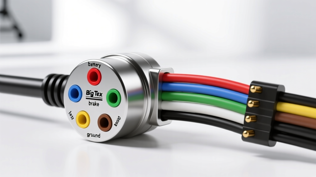
Introduction to Big Tex Electrical Systems
When it comes to heavy-duty hauling, Big Tex trailers are an industry standard. However, the electrical systems on these robust trailers take a beating from road debris, moisture, and heavy current loads. Whether you are upgrading a damaged harness, adding electric brakes to a vintage model, or simply trying to troubleshoot a faulty connection, understanding the exact Big Tex trailer wiring diagram is critical. This practical installation guide focuses on the 7-way RV blade connector (SAE J286 standard), which is the most common configuration for Big Tex equipment, dump, and car hauler trailers. We will cover wire gauge requirements, junction box mapping, breakaway switch integration, and real-world troubleshooting techniques used by professional automotive electricians.
The Standard 7-Way RV Blade Pinout
Before cutting any wires or stripping insulation, you must understand the standard 7-way RV blade pinout. Big Tex utilizes the industry-standard configuration for their factory-installed 7-pin plugs. This ensures compatibility with modern tow vehicles equipped with OEM brake controllers and trailer modules. Below is the definitive pinout chart, including the recommended American Wire Gauge (AWG) sizes to prevent voltage drop over the length of a 20-foot trailer tongue.
| Pin Position | Function | Standard Plug Wire Color | Minimum AWG |
|---|---|---|---|
| Pin 1 (Top Left) | Left Turn / Stop | Yellow | 14 AWG |
| Pin 2 (Bottom Left) | Reverse / Aux Power | Black or Purple | 12 AWG |
| Pin 3 (Center) | Ground (Chassis) | White | 10 AWG |
| Pin 4 (Top Right) | Right Turn / Stop | Green | 14 AWG |
| Pin 5 (Bottom Right) | Electric Brakes | Blue | 12 AWG |
| Pin 6 (Top Center) | Tail / Running Lights | Brown | 14 AWG |
| Pin 7 (Bottom Center) | 12V Aux / Battery Charge | Red or Black | 10 AWG |
Note: Always use stranded copper wire rated for automotive/marine use (GXL or TXL insulation). Never use solid household wire, as it will fatigue and snap from trailer vibration.
Inside the Big Tex Junction Box: Wire Mapping
One of the most confusing aspects for DIYers referencing a generic Big Tex trailer wiring diagram is the transition at the A-frame junction box. Big Tex typically uses a forward-facing, weather-resistant junction box mounted on the tongue. The molded 7-way plug harness enters this box, but the internal wire colors often do not match the standard plug colors. According to Big Tex Owner Resources, the internal harness relies on standard trailer wiring color codes, which can cause crossed circuits if you simply splice color-to-color.
| Plug Pin | Plug Wire Color | Junction Box Internal Harness Color |
|---|---|---|
| 1 (Left Turn) | Yellow | Yellow |
| 2 (Reverse) | Purple | Purple or Black |
| 3 (Ground) | White | White |
| 4 (Right Turn) | Green | Green |
| 5 (Brakes) | Blue | Blue |
| 6 (Tail Lights) | Brown | Brown |
| 7 (12V Aux) | Red | Black or Red |
Always verify continuity with a digital multimeter (DMM) from the plug face to the bare wire ends inside the junction box before crimping them to the terminal block. Factory wiring runs can occasionally feature substitute colors due to supply chain variations during manufacturing.
Step-by-Step 7-Pin Harness Installation
Step 1: Prepping the Tongue and Junction Box
Disconnect the trailer from the tow vehicle and remove the breakaway battery. Open the Big Tex junction box and remove the terminal block cover. Clean the terminal block contacts with electrical contact cleaner and a brass wire brush. If the block shows signs of severe galvanic corrosion (green/white crust), replace it with a new 7-post heavy-duty terminal strip. Apply a thin layer of dielectric grease to the screw threads to prevent future moisture ingress.
Step 2: Routing and Securing the Main Harness
Route the new 7-way harness along the inside of the A-frame tongue. Use split-loom tubing to protect the wires from road rocks and debris. Secure the loom using UV-resistant nylon zip ties every 12 to 18 inches. Avoid routing the harness near sharp metal edges or the coupler latch mechanism, where repetitive movement could sheer the insulation. Where the harness passes through the junction box knock-out, install a rubber grommet to prevent the metal box from cutting into the wire jacket.
Step 3: Terminating the Connections
Strip 5/16-inch of insulation from each wire. Crimp on vinyl-insulated ring terminals (size #10 stud) using a professional ratcheting crimper, such as the Knipex PreciForce. Never use cheap stamped-metal pliers for crimping; an improper crimp will lead to high resistance, heat buildup, and eventual failure. Place the ring terminals onto the corresponding terminal block posts and torque the nuts to 25-30 in-lbs. Over-tightening can strip the brass studs, while under-tightening will cause arcing.
Integrating Electric Brakes and Breakaway Switches
For Big Tex car haulers and equipment trailers equipped with electric drum brakes, the breakaway switch is a critical safety and legal requirement. The breakaway system requires a dedicated 12V battery (usually a 12V 5Ah Sealed Lead Acid battery) mounted in a weatherproof box on the tongue.
- Power Feed: Run a 12 AWG red wire from the positive terminal of the breakaway battery to one side of the breakaway switch.
- Brake Output: Run a 12 AWG blue wire from the other side of the breakaway switch and splice it inline with the blue electric brake wire (Pin 5) heading to the trailer axles.
- Grounding: Connect the negative terminal of the breakaway battery to the main white ground wire (Pin 3) or directly to the trailer frame using a self-tapping sheet metal screw and a star washer to bite through the paint.
When the pin is pulled, the switch closes, sending 12V directly to the brake magnets, locking the trailer wheels independently of the tow vehicle. For detailed brake controller calibration, refer to the Tekonsha Installation Guides for your specific proportional controller model.
Troubleshooting Common Big Tex Wiring Faults
Even with a perfect Big Tex trailer wiring diagram reference, environmental factors can cause electrical gremlins. Here is how to diagnose the most common issues using a professional diagnostic approach.
Voltage Drop and Grounding Issues
The number one cause of trailer light failure is a poor ground. If your tail lights dim when you hit the brakes, or your turn signals hyper-flash, you have a ground fault. Do not just check the plug; perform a voltage drop test. Set your Fluke multimeter to DC Volts. Place the red probe on the 12V source (Pin 7 or the tow vehicle battery positive) and the black probe on the trailer frame (bare metal). Turn on all trailer lights. A reading higher than 0.5V indicates excessive resistance in the ground circuit. Clean the frame contact point with a flap disc until bare steel is exposed, re-terminate the 10 AWG white wire, and coat with battery terminal protector spray.
Corrosion in the Junction Box
Big Tex trailers are frequently used in harsh environments, including winter road salt and marine applications. If the junction box seal fails, water pools at the bottom of the box, submerging the lower terminal posts (often the ground and auxiliary pins). Inspect the bottom drain hole of the junction box to ensure it is not clogged with dirt or spider webs. If corrosion is present, neutralize it with a baking soda and water solution, rinse with distilled water, dry completely, and pack the empty space inside the junction box with marine-grade dielectric grease to displace future moisture.
Electric Brake Drag or Weak Stopping
If your Big Tex trailer brakes feel weak or drag continuously, the issue may not be the mechanical shoes, but the wiring. Check the blue brake wire for chafing against the leaf springs or axle tubes. A short to ground will cause the brake controller to register a continuous load, sending a low-voltage current to the magnets and causing them to drag and overheat. Use an ohmmeter to check the resistance between the blue wire and the trailer ground. A healthy set of dual-axle electric brakes should read between 3.0 and 4.5 ohms total. An infinite reading (OL) indicates a broken wire, while a reading near 0.0 ohms indicates a dead short.
Final Verification and Safety Check
Before taking your Big Tex trailer onto the highway, perform a full functional test. Have an assistant verify the left turn, right turn, running lights, and brake lights while you monitor the tow vehicle's brake controller output. Finally, pull the breakaway switch lanyard to ensure the trailer brakes lock up firmly. By adhering to these professional installation standards and referencing the correct wiring schematics, you ensure your trailer's electrical system is as reliable and heavy-duty as the steel frame it is mounted to. For standardized pinout regulations, always consult the SAE J286 Trailer Connector Standard to ensure your rig remains DOT compliant across all 50 states.