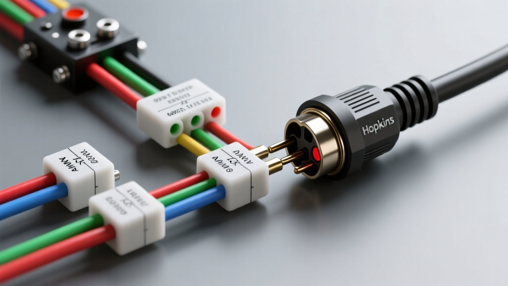
Introduction to the Hopkins 7-Way RV Standard
When towing heavy-duty travel trailers, fifth wheels, or equipment haulers, the 7-way RV blade connector is the undisputed industry standard. Among the myriad of manufacturers, Hopkins Manufacturing remains a dominant force, producing both OEM-style molded pigtails and heavy-duty hardwire junction boxes. Understanding the exact Hopkins 7 blade trailer plug wiring diagram is critical for ensuring safe brake controller integration, auxiliary battery charging, and proper lighting synchronization. Unlike the 7-way round connectors used in heavy agricultural and commercial trucking (which follow different SAE J560 standards), the 7-way blade adheres to the RVIA (Recreational Vehicle Industry Association) color-code and pinout matrix.
This advanced technical guide dissects the Hopkins 7-way blade architecture, detailing terminal assignments, American Wire Gauge (AWG) requirements for voltage drop mitigation, and advanced diagnostic protocols for resolving parasitic draws and ground faults.
Hopkins 7 Blade Trailer Plug Wiring Diagram: Pinout Matrix
The physical layout of the Hopkins 7 blade connector (such as the popular Hopkins 48197 or 47985 series) follows a standardized clock-face orientation when looking directly at the male plug (the piece attached to the trailer harness). Below is the definitive pinout matrix.
| Pin Position | Function | Standard Wire Color | Minimum AWG | Optimal AWG (Long Runs) |
|---|---|---|---|---|
| 7 o'clock (Pin 1) | System Ground | White | 10 AWG | 8 AWG |
| 5 o'clock (Pin 2) | Electric Brakes | Blue | 10 AWG | 8 AWG |
| 3 o'clock (Pin 3) | Tail / Running Lights | Brown | 14 AWG | 12 AWG |
| 1 o'clock (Pin 4) | 12V Auxiliary Power | Black (or Red) | 10 AWG | 8 AWG |
| 9 o'clock (Pin 5) | Left Turn / Stop | Yellow | 14 AWG | 12 AWG |
| 11 o'clock (Pin 6) | Right Turn / Stop | Green | 14 AWG | 12 AWG |
| Center (Pin 7) | Reverse / Center Aux | Purple (or Red) | 14 AWG | 12 AWG |
Detailed Pin Analysis & AWG Specifications
System Ground (White): The most common failure point in any trailer harness is the ground. The Hopkins 7 blade wiring diagram dictates that the white wire must complete the circuit for all lighting and auxiliary functions. While 10 AWG is standard, upgrading to 8 AWG stranded copper is highly recommended for fifth wheels exceeding 30 feet. The ground must be terminated directly to the trailer's main battery negative bus bar or a dedicated, bare-metal chassis ground bolted with a star washer to bite through paint and corrosion.
Electric Brakes (Blue): This circuit carries the modulated DC voltage from the tow vehicle's brake controller (e.g., Tekonsha Prodigy P3 or Redarc Tow-Pro Elite) to the trailer's electric brake magnets. Because brake magnets can draw up to 3-4 amps per axle (12-16 amps total for a triple-axle toy hauler), utilizing 10 AWG or 8 AWG wire is mandatory to prevent voltage drop, which directly results in delayed or weak braking performance.
12V Auxiliary (Black/Red): Used for charging the trailer's breakaway battery or powering interior 12V accessories while in transit. Voltage drop is the enemy here. If you are pushing 10 amps to charge a depleted deep-cycle battery over a 40-foot cable run, a standard 10 AWG wire will suffer a severe voltage drop, potentially starving the battery of the absorption-charge voltage it requires.
Calculating Voltage Drop for the 12V Auxiliary Circuit
To ensure your trailer's breakaway battery receives adequate charging voltage, you must calculate the voltage drop across the black auxiliary wire. The formula for DC voltage drop in a single-phase circuit is:
VD = (2 x K x I x L) / A
- VD = Voltage Drop
- K = Specific resistance of copper (12.9 ohms per circular mil foot at 75°C)
- I = Current in amps (e.g., 10A for battery charging)
- L = One-way length of the wire in feet (e.g., 40 ft from truck alternator to trailer battery)
- A = Cross-sectional area of the wire in circular mils (10 AWG = 10,380; 8 AWG = 16,510)
Using 10 AWG wire for a 40-foot run at 10 amps yields a voltage drop of approximately 0.99V. If your alternator outputs 14.2V, the trailer battery only sees 13.2V, which is insufficient for proper absorption charging. Upgrading to 8 AWG reduces the drop to 0.62V, delivering a healthy 13.58V to the trailer battery. This mathematical reality is why professional installers always oversize the auxiliary and ground circuits on the Hopkins 7 blade connector.
Terminal Termination: Inside the Hopkins Connector
When wiring a hardwire Hopkins 7-way plug (like the Hopkins 47985 junction box style or the screw-terminal molded plugs), the method of termination dictates the longevity of the connection. Most Hopkins blade plugs utilize set-screw terminals rather than solder cups.
The Danger of Galvanic Corrosion and Strand Fraying
Stripped wire ends inserted directly under a set screw will inevitably fray. As the trailer navigates highway vibrations, the copper strands shear against the steel or brass set screw, increasing electrical resistance. Furthermore, dissimilar metal corrosion (galvanic corrosion) between the copper wire and the brass terminal will create a high-resistance patina over time.
Best Practice Protocol:
- Strip the wire precisely to the terminal depth (usually 3/8 inch).
- Crimp a high-quality, heat-shrink insulated ring terminal or ferrule onto the wire using a ratcheting crimper (e.g., Titan or Wirefy).
- If the Hopkins plug requires direct wire insertion, tin the stripped ends with rosin-core solder to bind the strands, but avoid excessive solder that can cause cold-flow under the set screw.
- Apply a liberal coating of NO-OX-ID A-Special conductive grease to the terminal block before sealing the housing with dielectric silicone.
Advanced Troubleshooting: Ground Faults & Voltage Drop Testing
Relying on a simple 12V test light is insufficient for diagnosing modern towing electrical systems. A test light draws negligible current and will illuminate even on a high-resistance, failing circuit. Advanced diagnostics require a digital multimeter (DMM) and a load-testing approach.
Diagnostic Decision Tree for Hopkins 7-Way Failures
Symptom: Trailer running lights (Brown) illuminate, but blink erratically or dim when the turn signal (Yellow/Green) is activated.
- Cause: This is a classic backfeed ground fault. The turn signal circuit is seeking a path to ground through the running light circuit because the primary white ground wire has failed or exhibits high resistance.
- Test: Set your DMM to DC Volts. Connect the black probe to the trailer's bare chassis and the red probe to the Hopkins plug's ground pin (Pin 1). Have an assistant turn on the tow vehicle's headlights and turn signals.
- Fix: If the DMM reads more than 0.2V between the plug ground and the trailer chassis, the ground path is compromised. Clean the chassis ground point, replace the star washer, and verify the white wire continuity back to the tow vehicle's battery negative.
Symptom: Electric brakes (Blue) feel weak or the brake controller displays an S.H. (Short) or O.L. (Open Loop) code intermittently over bumps.
- Cause: Intermittent continuity loss in the blue wire, usually at the Hopkins plug set-screw or the trailer's breakaway switch.
- Test: Perform a voltage drop test on the blue circuit under load. Backprobe the brake controller output and measure voltage at the trailer brake magnets while manually applying the controller slide.
- Fix: A voltage drop greater than 1.0V indicates high resistance. Inspect the Hopkins 7 blade connector's blue terminal for loose set screws or green copper oxide corrosion. Re-terminate using ferrules and conductive grease.
Integration with Modern Tow Vehicle Multiplex Systems
Modern trucks (e.g., 2015+ Ford Super Duty, GM HD, and Ram Heavy Duty) utilize multiplexed CAN-bus systems and solid-state smart relays for trailer lighting. These systems monitor current draw to detect faults. If you are adapting a Hopkins 7 blade trailer plug wiring diagram to an older trailer with high-draw incandescent bulbs, the smart relay may interpret the initial inrush current as a short circuit, shutting down the circuit entirely.
To resolve this, bypass the factory smart-relay harness using a dedicated high-amperage relay kit powered directly from the tow vehicle's battery, or upgrade the trailer's lighting to low-draw LED assemblies, which drastically reduce the amperage footprint and prevent CAN-bus fault codes.
Authoritative References & Standards
For further engineering specifications regarding trailer wiring and connector standards, consult the following industry authorities:
- Recreational Vehicle Industry Association (RVIA) - Best practices for RV low-voltage wiring standards and color-code compliance.
- Hopkins Manufacturing Corporation - OEM specifications, torque limits for set-screw terminals, and molded harness tear-downs.
- eTrailer Wiring FAQ & Technical Guides - Real-world application data, voltage drop calculators, and brake controller integration matrices.