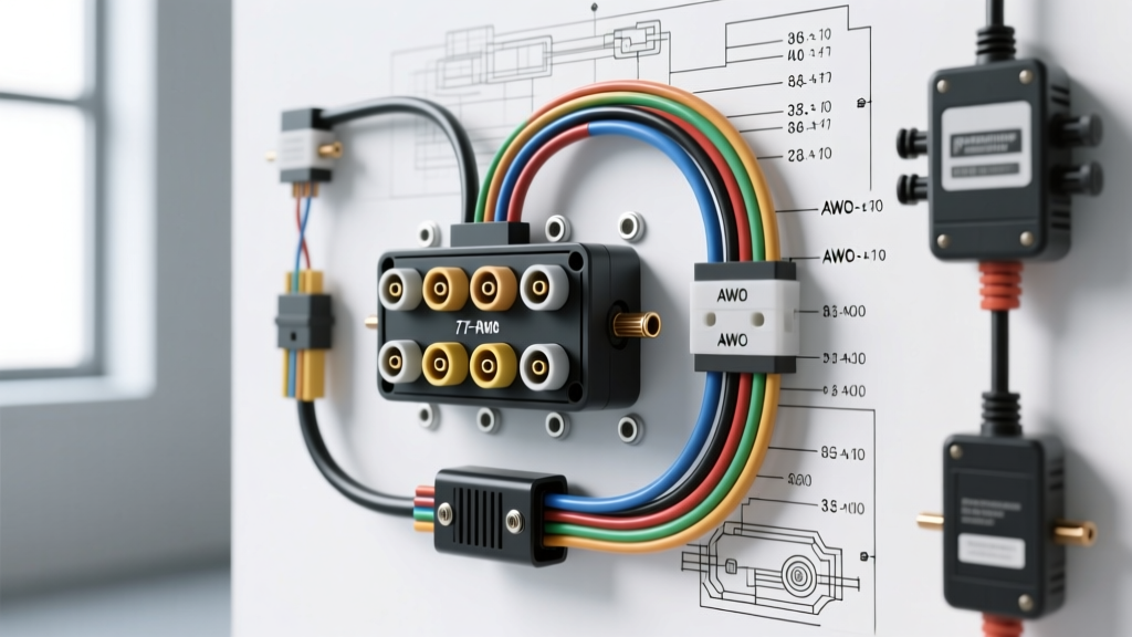
The True Cost of Brake Controller Failures
When towing heavy loads, a malfunctioning brake system is not just an inconvenience; it is a critical safety hazard. Diagnosing electric trailer brake controller problems requires a systematic approach to isolate whether the fault lies within the cab-mounted unit, the vehicle's tow package wiring, the 7-way connector, or the trailer's axle hubs. Many owners immediately assume the controller is dead and purchase a replacement, only to find the new unit displays the exact same error codes. This misdiagnosis leads to wasted money and unsafe towing conditions.
From an automotive electrical perspective, resolving these issues requires understanding Pulse Width Modulation (PWM) signals, voltage drop testing, and SAE J286 pinout standards. This guide provides a comprehensive cost and tool requirements analysis to help you accurately diagnose, repair, and budget for electric brake system failures.
Essential Diagnostic Tools & Equipment Budget
Before swapping out components, you must verify circuit integrity. Modern proportional brake controllers (like the Tekonsha Prodigy P3 or Curt Spectrum) utilize microprocessors that are highly sensitive to voltage fluctuations and high-resistance grounds. Relying on a basic $5 test light is insufficient for modern CAN-bus integrated tow modules.
Tool Cost Breakdown & Specifications
| Tool / Equipment | Purpose | Estimated Cost | Expert Requirement Notes |
|---|---|---|---|
| Digital Multimeter (DMM) | Voltage drop, continuity, and PWM signal verification | $40 - $250 | Must have min/max recording and a fast refresh rate to capture PWM pulses. |
| Incandescent Circuit Tester | Load-testing 12V power and ground circuits | $15 - $25 | Do NOT use LED testers. LEDs draw negligible current and will not reveal high-resistance grounds or corroded pins. |
| Wire Strippers & Crimpers | Terminal replacement and harness repair | $30 - $80 | Must accommodate 10 AWG and 12 AWG wire with insulated barrel crimps. |
| Adhesive-Lined Heat Shrink | Weatherproofing splices and preventing corrosion | $15 - $30 | Standard electrical tape fails under chassis heat and vibration. Use 3:1 shrink ratio with internal sealant. |
| Dielectric Grease | Preventing galvanic corrosion in 7-way sockets | $8 - $15 | Apply sparingly to the male pins of the trailer plug, not the female sockets, to avoid pushing grease into the contacts. |
SAE J286 7-Way RV Blade Pinout & Wire Gauge Specs
Most electric trailer brake controller problems stem from the 7-way RV blade connector. Cross-talk between pins, melted plastic housings, and undersized wiring are the primary culprits. Below is the standard RV 7-way pinout. Note that commercial and agricultural 7-way pinouts differ significantly.
| Pin | Function | Standard Wire Color | Minimum AWG | Common Failure Mode |
|---|---|---|---|---|
| 1 | Ground (Chassis) | White | 10 AWG (8 AWG preferred) | Corrosion at frame bolt causing 'S.H.' errors and erratic braking. |
| 2 | Electric Brakes | Blue | 10 AWG | Chafed insulation near axle; shorting to the frame. |
| 3 | Tail / Running Lights | Green | 12 AWG | Melted connector causing backfeed into the brake circuit. |
| 4 | 12V Auxiliary / Battery Charge | Black | 10 AWG | Voltage drop due to undersized factory wiring; dead controller screen. |
| 5 | Right Turn / Stop | Brown | 12 AWG | Blown fuse due to trailer light short. |
| 6 | Left Turn / Stop | Red | 12 AWG | T-tap splice failure at the CHMSL brake switch circuit. |
| 7 | Reverse Lights / Aux | Yellow | 12 AWG | Rarely causes brake issues unless shorted to Pin 2. |
Common Electric Trailer Brake Controller Problems & Wiring Checks
1. 'S.H.' (Short Circuit) or 'O.L.' (Overload) Errors
When the display reads 'S.H.', the controller has detected a direct short to ground on the blue brake output wire (Pin 2). To isolate this, perform a split-diagnostic test:
- Unplug the trailer. If the 'S.H.' code remains on the truck's display, the short is in the vehicle's wiring harness between the controller and the rear bumper.
- If the code disappears, the short is on the trailer. Inspect the blue wire routing from the tongue to the axles. Look for pinch points where the wire passes through the torsion axle brackets or where zip-ties have cut through the insulation.
- Check the Breakaway Switch. The breakaway switch is wired in parallel with the brake output wire. If the internal plunger is stuck or the switch is filled with moisture, it will create a dead short. Disconnect the breakaway switch and retest. For deeper insights on switch failures, refer to the etrailer Wiring FAQ.
2. Dead Screen or Intermittent Power Loss
A controller that randomly shuts off or fails to power on is rarely a bad unit; it is almost always a voltage drop issue on the 12V supply (Pin 4, Black) or the Ground (Pin 1, White).
- The Voltage Drop Test: Set your DMM to DC Volts. Place the red probe on the vehicle battery's negative terminal and the black probe on the controller's ground wire (or Pin 1 on the bumper). Have an assistant press the brake pedal or manual override. If the DMM reads higher than 0.15V under load, your ground circuit has excessive resistance.
- The Fix: Remove the ground ring terminal from the chassis. Sand the metal to bare steel using 80-grit sandpaper, apply a thin layer of anti-seize or dielectric grease over the bare metal *after* tightening, and torque the M8 bolt to 15-20 Nm. Never ground a brake controller to painted sheet metal or a plastic bumper support.
3. Brakes Lock Up When Headlights Are Turned On
This is a classic symptom of cross-talk inside a degraded 7-way socket. The tail light circuit (Pin 3, Green) and the brake circuit (Pin 2, Blue) are physically adjacent inside the plug. Over time, water intrusion and high amperage draw from incandescent trailer running lights cause the internal plastic dividers to melt. When you turn on the headlights, 12V bleeds from Pin 3 into Pin 2, commanding the trailer brakes to lock. The only reliable fix is cutting off the molded plug and hardwiring a heavy-duty, corrosion-resistant 7-way replacement plug with solid brass pins.
Repair vs. Replace: Cost Analysis
Understanding the financial breakdown of repairs helps you decide whether to troubleshoot the harness or replace the hardware. Below is a realistic cost analysis based on current aftermarket and OEM pricing.
| Component / Service | DIY Cost (Parts Only) | Dealer/Shop Cost (Parts + Labor) | Notes |
|---|---|---|---|
| Proportional Controller (e.g., Tekonsha P3) | $140 - $170 | $250 - $350 | Time-delayed units are cheaper ($60) but cause brake grab and overheating. |
| Plug-and-Play Wiring Adapter (OEM Port) | $25 - $40 | $80 - $120 | Eliminates the need to splice into the CHMSL brake switch wire. |
| 7-Way RV Socket Replacement (Vehicle Side) | $30 - $50 | $150 - $250 | Requires dropping the bumper or cutting into the factory tow harness. |
| Trailer Axle Wiring Harness Repair | $20 - $40 | $120 - $180 | Includes 10 AWG wire, heat shrink, and new quick-connect plugs. |
| Magnet & Hub Assembly Replacement (Per Axle) | $45 - $80 | $200 - $300 | Required if a shorted magnet has burned out internally (reads < 2 Ohms). |
Expert Wiring & Grounding Best Practices
To permanently eliminate recurring electric trailer brake controller problems, adhere to these master-technician standards:
- Avoid T-Taps: Never use scotch locks or T-taps to splice the controller's red stoplight wire into the vehicle's CHMSL circuit. These pierce the wire insulation, inviting capillary corrosion that eventually severs the copper strands. Use a dedicated OEM plug-and-play harness or strip the wire, solder the connection, and seal it with adhesive-lined heat shrink.
- Upgrade the 12V Feed: Many factory tow packages use 12 AWG wire for the 12V auxiliary pin (Pin 4). If you are towing a trailer with a breakaway battery or interior lights, this wire will suffer from severe voltage drop over a 20-foot run. Run a dedicated 10 AWG wire directly from the battery positive terminal to Pin 4, protected by a 30-amp auto-reset circuit breaker mounted within 18 inches of the battery.
- Test the Magnets: If the wiring tests perfectly but the controller still shows an overload, test the trailer brake magnets. Disconnect the trailer plug and use your DMM to measure resistance across the blue and white wires on the trailer plug. A healthy 10-inch magnet should read between 3.0 and 4.0 Ohms. If it reads near 0 Ohms, the internal coil has shorted and the magnet must be replaced. For detailed magnet testing procedures, consult the Tekonsha Troubleshooting Guide.
By investing in the correct diagnostic tools and understanding the specific AWG and pinout requirements of your towing setup, you can accurately pinpoint failures, save hundreds of dollars in unnecessary dealer diagnostics, and ensure your trailer stops safely every time.