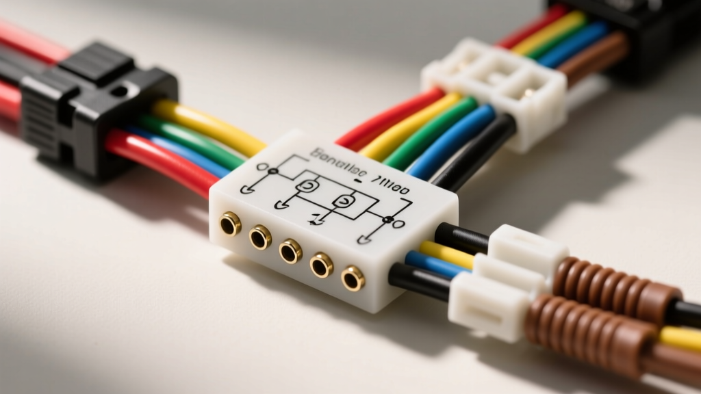
Introduction to the 7-Way RV Blade Connector
When towing heavy-duty trailers, fifth wheels, or large travel trailers, a standard 4-way flat connector simply does not provide the necessary circuits for electric brakes, auxiliary 12V power, and reverse lights. The 7-way RV blade connector is the undisputed industry standard for these applications. Understanding the exact pinout, wire gauge requirements, and routing best practices is critical for a safe and legally compliant tow rig. In this complete 7 pin trailer plug wiring harness walkthrough, we will dissect every circuit, outline the SAE-compliant color codes, and provide expert-level installation advice to prevent voltage drop and ground faults.
Step-by-Step 7 Pin Trailer Plug Wiring Harness Walkthrough
The standard 7-way blade connector (often referred to as the RV blade) follows a specific clock-face orientation when looking at the vehicle-side socket or the trailer-side plug. Below is the comprehensive circuit breakdown.
Pin 1: Ground (White) - 7 O'Clock Position
Function: Completes the electrical circuit for all lighting and brake functions.
Wire Color: White
Recommended AWG: 10 AWG (Minimum)
Expert Insight: The most common cause of trailer lighting failure is a poor ground. Never rely solely on the hitch ball and coupler for grounding, as rust, grease, and paint act as insulators. Run a dedicated 10 AWG white wire from Pin 1 directly to a clean, bare-metal point on the vehicle frame, or ideally, directly to the negative battery terminal. On the trailer side, ensure the white wire is bonded to the trailer frame near the tongue and to the chassis of every individual light fixture to prevent 'ground bounce' and dimming when the brakes are applied.
Pin 2: Tail and Running Lights (Brown) - 5 O'Clock Position
Function: Powers the trailer's taillights, side marker lights, and clearance lights.
Wire Color: Brown
Recommended AWG: 14 AWG (12 AWG for trailers over 30 feet)
Expert Insight: Because the brown wire must power multiple LED or incandescent fixtures across a long trailer frame, voltage drop is a real concern. If you are wiring a 35-foot fifth wheel, upgrade the main brown trunk line to 12 AWG, then step down to 16 AWG pigtails for the individual marker lights. Always use heat-shrink butt connectors rather than standard vinyl crimps to prevent moisture ingress, which causes copper oxidation and high resistance.
Pin 3: Left Turn Signal and Stop Lamps (Yellow) - 9 O'Clock Position
Function: Controls the left-side turn signal and left brake light.
Wire Color: Yellow
Recommended AWG: 14 AWG
Expert Insight: In standard North American wiring, the turn signal and brake light share the same filament or LED circuit. If your vehicle uses separate brake and turn signals (common in many modern European imports and some domestic trucks), you will need to install a 3-to-2 wire tail light converter module before the harness reaches the 7 pin trailer plug wiring harness socket to combine these signals properly.
Pin 4: 12V Auxiliary Power (Black) - 1 O'Clock Position
Function: Provides continuous 12V power to charge the trailer's breakaway battery, power interior lights, or run a winch.
Wire Color: Black
Recommended AWG: 10 AWG (8 AWG for high-draw accessories)
Expert Insight: This circuit draws directly from the vehicle's battery. It is an absolute safety requirement to install a 40-amp auto-resetting circuit breaker within 18 inches of the vehicle's positive battery terminal. If a short occurs in the trailer's 12V system, the breaker will trip and prevent a harness fire. Do not route the black 12V wire parallel to the blue brake wire for long distances to avoid electromagnetic interference (EMI).
Pin 5: Right Turn Signal and Stop Lamps (Green) - 3 O'Clock Position
Function: Controls the right-side turn signal and right brake light.
Wire Color: Green
Recommended AWG: 14 AWG
Expert Insight: Similar to the yellow wire, the green wire handles combined brake and turn functions. When testing this circuit with a multimeter, expect to see 12V DC when the brake pedal is depressed, and a pulsing 12V signal when the right turn signal is engaged. If the right turn signal hyper-flashes inside the tow vehicle's cabin, it usually indicates a blown bulb on the trailer's right side or a high-resistance connection in the green wire.
Pin 6: Electric Brakes (Blue) - 11 O'Clock Position
Function: Carries the variable DC voltage from the tow vehicle's brake controller to the trailer's electric brake magnets.
Wire Color: Blue
Recommended AWG: 10 AWG (Strictly required for 2-axle; 8 AWG for 3-axle trailers)
Expert Insight: Electric brake magnets can draw up to 3.5 amps each. A dual-axle trailer with four magnets can pull 14 amps continuously during a hard stop. Using 14 AWG wire for the blue brake circuit will result in severe voltage drop, causing the trailer brakes to engage weakly or not at all. Furthermore, because proportional brake controllers use Pulse Width Modulation (PWM) to vary braking force, a standard incandescent test light will not accurately diagnose this circuit. Use a digital multimeter or a dedicated LED brake controller tester.
Pin 7: Reverse Lights and Auxiliary (Purple) - Center Pin
Function: Powers trailer reverse lights or activates an electric reverse lockout on hydraulic surge brake couplers.
Wire Color: Purple
Recommended AWG: 14 AWG
Expert Insight: The purple wire is energized only when the tow vehicle is shifted into reverse. If you are wiring a boat trailer with hydraulic surge brakes, this wire connects to a reverse lockout solenoid to prevent the brakes from engaging while backing down a boat ramp. Ensure the solenoid is properly sealed, as it is highly exposed to water and road salt.
Wire Gauge (AWG) Specifications & Routing Best Practices
Selecting the correct American Wire Gauge (AWG) is non-negotiable for a safe 7 pin trailer plug wiring harness installation. The chart below outlines the minimum requirements based on standard SAE guidelines and real-world amperage draws.
| Circuit Function | Wire Color | Standard AWG | Heavy-Duty AWG (30ft+) | Max Continuous Amperage |
|---|---|---|---|---|
| Ground | White | 10 AWG | 8 AWG | 30A - 40A |
| Tail/Running Lights | Brown | 14 AWG | 12 AWG | 15A |
| Left Turn/Brake | Yellow | 14 AWG | 12 AWG | 15A |
| 12V Auxiliary | Black | 10 AWG | 8 AWG | 30A (Fused at 40A) |
| Right Turn/Brake | Green | 14 AWG | 12 AWG | 15A |
| Electric Brakes | Blue | 10 AWG | 8 AWG | 20A - 30A |
| Reverse/Aux | Purple | 14 AWG | 12 AWG | 15A |
Physical Routing and Sealing Protocols
When routing the main harness from the front of the trailer tongue to the rear axle, never run the wires directly alongside sharp frame edges or near exhaust components. Use split-loom corrugated tubing to protect the bundle from road debris and UV degradation. Secure the loom every 18 inches using UV-resistant zip ties or stainless steel P-clamps. At the 7-way plug termination point, apply a generous amount of dielectric grease inside the connector housing to displace moisture and prevent galvanic corrosion between the brass pins and the copper wire crimps.
Troubleshooting Common 7-Way Harness Failures
Even with a meticulous installation, environmental factors and physical wear can cause faults. Use this diagnostic tree to isolate issues quickly:
- Symptom: All trailer lights dim or flicker when the brake pedal is pressed.
Cause: Ground wire bottleneck or 'ground bounce'. The white wire cannot handle the combined amperage of the brake lights and running lights simultaneously.
Fix: Upgrade the white ground wire to 8 AWG and add secondary ground pigtails at the rear light assemblies. - Symptom: Trailer brakes lock up abruptly or do not engage smoothly.
Cause: Voltage drop on the blue brake wire, or the brake controller is reading a faulty ground signal.
Fix: Check for corrosion at Pin 6. Verify the blue wire is 10 AWG or thicker. Ensure the brake controller's ground wire is attached to a clean, unpainted metal surface under the dash. - Symptom: The 12V auxiliary circuit is dead at the trailer plug.
Cause: Tripped 40A circuit breaker near the vehicle battery, or a blown inline fuse in the tow vehicle's under-hood fuse box.
Fix: Test for 12V at the output side of the auto-reset breaker. If dead, replace the breaker. If power is present at the breaker but not at Pin 4, trace the black wire for a severed connection or rodent damage.
Authoritative References
For further technical validation and vehicle-specific towing module programming, consult the following industry standards and manufacturer resources:
- SAE International - SAE J286: Trailer Lighting Standards (Provides the foundational engineering requirements for trailer lighting circuits and connector configurations).
- etrailer.com - Comprehensive Trailer Wiring FAQ and Diagrams (An industry-leading database for vehicle-specific tow package wiring and 7-way adapter solutions).
- Tekonsha - Brake Controller Installation and Wiring Guides (Authoritative documentation on integrating PWM brake controllers with 7 pin trailer plug wiring harness setups).