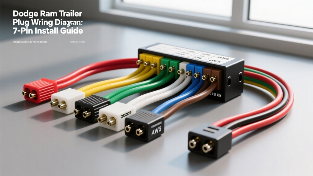
Introduction to the Dodge Ram Trailer Plug Wiring Diagram
Whether you are restoring a corroded factory connector on a 3rd-generation Ram or adding a heavy-duty towing harness to a newer 5th-generation model, understanding the correct Dodge Ram trailer plug wiring diagram is critical for safety and functionality. The 7-pin RV blade connector is the industry standard for towing enclosed trailers, car haulers, and campers with electric brakes. Unlike simpler 4-pin flat connectors, the 7-way setup requires dedicated circuits for auxiliary power, reverse lights, and proportional electric braking.
Modern Dodge Rams (particularly 2006 and newer) utilize a Totally Integrated Power Module (TIPM) to manage vehicle electronics. Incorrect splicing, excessive current draw, or poor grounding can permanently damage the TIPM's internal micro-relays. This practical how-to installation guide provides the exact wire color codes, AWG specifications, and step-by-step procedures to install or repair your 7-pin harness without compromising your truck's electrical architecture.
Standard 7-Pin RV Blade Pinout and Specifications
Before cutting or splicing any wires, you must understand the standard SAE J286 / RVIA 7-way blade configuration. The physical layout of the plug on your Dodge Ram dictates the following pinout. Always verify with a multimeter before connecting a new pigtail, as aftermarket harnesses occasionally deviate from standard color codes.
| Pin Location | Function | Standard Wire Color | Minimum AWG | Circuit Notes |
|---|---|---|---|---|
| Center Bottom (7) | Reverse / Aux | Purple | 12 AWG | Often tied to reverse lights or backup solenoids. |
| Center Left (5) | Electric Brakes | Blue | 10 AWG | Direct feed from the brake controller. 8 AWG recommended for 3-axle trailers. |
| Center Right (6) | 12V Auxiliary Power | Black (or Red) | 10 AWG | Constant 12V hot for charging trailer breakaway batteries or interior lights. |
| Bottom Left (3) | Ground | White | 8 AWG | Must be grounded to a clean, bare metal point on the Ram's frame. |
| Bottom Right (4) | Tail / Running Lights | Brown | 12 AWG | Monitored by the TIPM on newer Rams; sensitive to LED current drops. |
| Top Left (1) | Left Turn / Stop | Yellow | 12 AWG | Combined stop/turn signal for the left side of the trailer. |
| Top Right (2) | Right Turn / Stop | Green | 12 AWG | Combined stop/turn signal for the right side of the trailer. |
Reference: For deeper insights into RVIA low-voltage standards and color code variations, consult the RVIA Low Voltage Standards documentation.
Essential Tools and Materials
Do not use cheap vinyl tape or Scotchlok T-tap connectors. Automotive trailer wiring is exposed to moisture, road salt, and extreme vibration. You will need:
- Wire: GXL (Cross-linked polyethylene) automotive primary wire in 8, 10, and 12 AWG.
- Connectors: Polyolefin adhesive-lined heat shrink butt connectors (3M or equivalent). The internal adhesive melts and seals the wire strands against capillary moisture intrusion.
- Crimpers: A ratcheting wire crimper with nested dies for 8-12 AWG terminals.
- Grounding Hardware: 3/8-inch stainless steel ring terminals, star washers, and anti-corrosion compound (e.g., OxGard).
- Protection: Split-loom tubing, zip ties, and dielectric silicone grease for the plug housing.
Step-by-Step 7-Pin Harness Installation Guide
Step 1: Disconnect Power and Route the Harness
Disconnect the negative battery terminal on your Dodge Ram to prevent accidental shorts against the TIPM or chassis. Route the new 7-pin pigtail harness from the rear bumper mounting bracket forward along the driver-side frame rail. Keep the wiring at least 6 inches away from the exhaust system to prevent the insulation from melting. Secure the harness with UV-resistant zip ties every 12 inches, and wrap the entire length in split-loom tubing to protect against road debris and rock strikes.
Step 2: Splicing and Crimping the Circuits
If you are replacing a damaged OEM pigtail, cut the old wires back to clean, uncorroded copper. Strip 5/16-inch of insulation from both the harness and truck-side wires. Slide the adhesive-lined heat shrink butt connector over the wire, insert the stripped ends into the metal barrel, and crimp firmly. Apply heat evenly with a heat gun until the polyolefin shrinks tightly and the adhesive seeps out of both ends. This creates a watertight, vibration-proof seal that meets etrailer's heavy-duty wiring specifications.
Step 3: Establishing a True Chassis Ground
The white ground wire is responsible for completing the circuit for all lighting functions. A poor ground is the number one cause of trailer light failure, hyper-flashing, and back-feeding (e.g., running lights turning on when you hit the brakes). Locate a thick, unpainted section of the Dodge Ram's frame rail near the rear bumper. Use a wire brush or sandpaper to remove all paint, powder coat, and rust down to bare steel. Attach an 8 AWG ring terminal to the white wire, place a stainless steel star washer between the terminal and the bare frame, and bolt it down. Torque the ground bolt to 18-22 ft-lbs to ensure it does not vibrate loose, then coat the terminal with anti-corrosion compound.
Step 4: Finalizing the Plug Housing
Once all wires are routed and spliced, pack the rear cavity of the 7-pin plug housing with dielectric silicone grease. This prevents moisture from wicking into the pins and causing galvanic corrosion between the copper wires and the brass terminals. Secure the housing cap and mount it to the bumper bracket using stainless steel hardware.
Integrating the Dodge Ram Brake Controller
For 4th-generation (2009-2018) and 5th-generation (2019+) Dodge Rams equipped with the factory tow package, you do not need to splice into the rear brake light switch. The manufacturer provides a dedicated blunt-cut pigtail tucked behind the driver-side kick panel or under the dash near the steering column. This pigtail typically contains four wires:
- White: Ground (Connect to chassis or brake controller ground)
- Black: 12V Constant Power (Connect to brake controller power input)
- Blue: Brake Output (Connects directly to Pin 5 on the rear 7-pin plug)
- Red / Light Green: Stoplight Switch Signal (Connects to the brake controller's red input wire)
When wiring a proportional brake controller (like a Tekonsha Prodigy or Redarc Tow-Pro), ensure the Blue brake output wire is a continuous, unbroken 10 AWG run from the dash controller to the rear bumper. Voltage drop over the 20+ foot length of the truck will severely reduce braking force at the trailer axles if a thinner 12 AWG wire is used.
Troubleshooting Common Ram Wiring and TIPM Faults
Dodge Rams are notorious for specific electrical quirks when towing. Use this diagnostic tree to resolve common issues after installing your 7-pin diagram harness:
Symptom: TIPM 'Trailer Disconnected' Message or Tail Light Failure
Cause: Modern Ram TIPMs use solid-state switching and current-sensing algorithms to detect if a trailer is plugged in. If you are using an all-LED trailer, the current draw on the brown (running light) circuit may be as low as 0.5 amps. The TIPM requires a minimum threshold (often around 2.0 amps) to recognize the trailer and close the internal relay.
Fix: Install a powered tail light converter module (like a Curt or Tekonsha powered modulator) that draws power directly from the Ram's battery via a 20-amp inline fuse, using the truck's brown wire only as a low-current trigger signal. Alternatively, install 50-ohm, 50-watt load resistors on the trailer's running light circuit to simulate an incandescent bulb draw.
Symptom: Electric Brakes Lock Up When Headlights Are Turned On
Cause: A classic 'back-feed' issue caused by a poor ground at the trailer or the Ram's rear harness. When the brown (tail light) circuit is energized, the current seeks a path to ground. Because the white ground wire has high resistance (due to corrosion or a loose bolt), the current travels backward through the blue (brake) circuit, falsely energizing the trailer's brake magnets.
Fix: Do not replace the brake controller. Instead, re-terminate the white ground wire at the Ram's frame and the trailer's A-frame tongue. Ensure both grounding points are sanded to bare, shiny metal and torqued properly.
Symptom: 12V Auxiliary Pin (Pin 6) Has No Power
Cause: On many Dodge Rams, the black 12V auxiliary wire at the rear bumper is not 'hot' by default. It is tied to a relay in the engine bay fuse box that is only activated when the ignition is in the 'RUN' position, or it requires a specific fuse to be installed by the dealer to activate the factory tow package aux circuit.
Fix: Check the Ram's owner manual for the 'Trailer Aux Power' fuse location in the under-hood PDC (Power Distribution Center). If the fuse and relay are present, test for voltage at Pin 6 with the ignition on. If upgrading to charge a heavy trailer battery, run a dedicated 8 AWG wire from the Ram's alternator/battery post with a 40-amp circuit breaker, bypassing the factory wiring to prevent overloading the OEM traces.