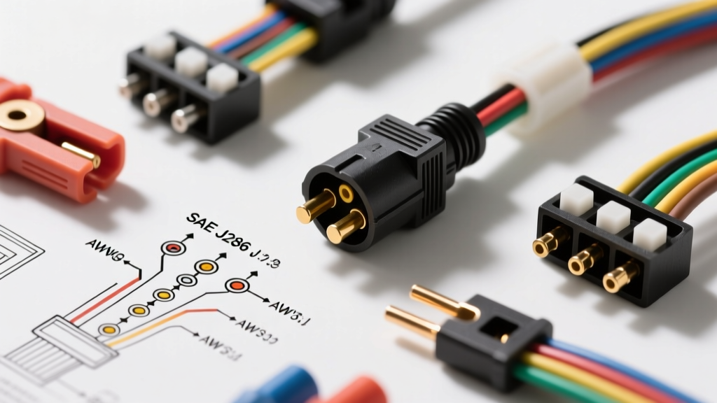
Introduction to the SAE J286 7-Way RV Blade Connector
The 7-way RV blade connector is the undisputed North American standard for recreational vehicles, car haulers, and heavy utility trailers. Governed by the SAE J286 standard, this connector provides the necessary circuits for lighting, electric brakes, and auxiliary power. However, simply matching wire colors is insufficient for heavy-duty applications. An advanced technical approach requires understanding Pulse Width Modulation (PWM) brake signals, voltage drop calculations over long harness runs, and proper environmental sealing to prevent galvanic corrosion.
This deep dive explores the exact pinout, AWG sizing requirements, and advanced integration techniques for brake controllers and auxiliary charging circuits. Whether you are wiring a 30-foot fifth-wheel or retrofitting a heavy-duty equipment trailer, adhering to these specifications ensures reliable operation and prevents catastrophic ground-fault failures.
Comprehensive 7 Pin Plug Wiring Diagram & Pinout Table
The physical layout of the 7-way trailer plug (trailer side) follows a specific clock-face orientation. Below is the definitive reference chart for SAE J286 compliance, including standard and heavy-duty AWG recommendations based on continuous amperage loads and voltage drop mitigation.
| Pin / Clock Position | Function | Standard Wire Color | Min. AWG | Heavy-Duty AWG | Circuit Type |
|---|---|---|---|---|---|
| Center | Reverse Lights / Aux | Purple | 14 | 12 | Continuous / Momentary |
| 1:00 (Top Right) | Ground Return | White | 10 | 8 | Common Ground |
| 3:00 (Right) | Tail / Running Lights | Brown | 14 | 12 | Continuous |
| 5:00 (Bottom Right) | Right Turn / Stop | Green | 14 | 12 | Intermittent |
| 7:00 (Bottom Left) | Electric Brakes | Blue | 12 | 10 | PWM / High Draw |
| 9:00 (Left) | Left Turn / Stop | Yellow | 14 | 12 | Intermittent |
| 11:00 (Top Left) | 12V Aux / Battery Charge | Black (or Red) | 10 | 8 (or 6) | Continuous High Draw |
Pin 1 (Ground): The Critical Return Path
The white wire at the 1:00 position is the most common point of failure in trailer wiring. Never rely on the hitch ball or safety chains for a ground return. The ground wire must be a dedicated 8 AWG or 10 AWG conductor routed directly from the plug to a centralized, bare-metal grounding bus on the trailer chassis. All trailer lighting and brake magnets must return to this bus, creating a star-ground topology that prevents ground loops and phantom voltage issues.
Electric Brake Circuit (Pin 5) & PWM Signal Integrity
The blue wire at the 7:00 position supplies power to the trailer's electric brake magnets. Modern proportional brake controllers, such as the Tekonsha Prodigy P3, do not output a simple 12V DC signal. Instead, they utilize a 3-axis accelerometer to calculate deceleration and output a 12V Pulse Width Modulated (PWM) square wave.
The duty cycle of this PWM signal dictates the braking torque. If the blue wire is undersized (e.g., using 14 AWG instead of the recommended 10 AWG), the inherent capacitance of a 25-to-30-foot wire run will distort the PWM square wave. This capacitance rounds off the sharp edges of the signal, leading to delayed brake magnet engagement, erratic braking, and excessive heat generation in the brake controller's internal MOSFETs.
- Wire Type: Use SXL (Cross-linked polyethylene) or GXL automotive wire for high-temperature and abrasion resistance.
- AWG Sizing: 10 AWG is mandatory for trailers with dual-axle (4 magnet) or triple-axle (6 magnet) configurations to handle peak transient currents exceeding 20 amps.
12V Auxiliary (Pin 6) & Voltage Drop Calculations
The 11:00 pin (Black or Red) provides 12V auxiliary power, typically used to charge a trailer breakaway battery, power interior lights, or maintain a house battery bank. This circuit is highly susceptible to voltage drop due to the long distance between the tow vehicle's alternator and the trailer battery.
Consider a scenario where a trailer battery draws 10A through 25 feet of 10 AWG copper wire (50 feet total round-trip). Using the standard voltage drop formula: VD = (2 x K x I x L) / A (where K=12.9 for copper, I=10A, L=25ft, A=10380 circular mils for 10 AWG), the voltage drop is approximately 1.24V. If the tow vehicle's alternator outputs 13.8V, only 12.56V reaches the trailer. This is insufficient for the absorption charging phase of a lead-acid battery, which requires 14.4V.
The Continuous-Duty Solenoid Solution
To prevent the trailer from draining the tow vehicle's starting battery when parked, the 12V auxiliary circuit must be gated. Install a continuous-duty solenoid (e.g., Pollak PK4210) under the hood of the tow vehicle. Wire the solenoid's activation coil to an ignition-switched 12V source. This ensures the 7-pin plug only receives auxiliary power when the engine is running, protecting the vehicle's BCM (Body Control Module) from parasitic draws and alternator overload.
Reverse / Auxiliary Pin (Center) & Backfeed Protection
The center pin (Purple) is designated for reverse lights or auxiliary functions. On trailers with hydraulic surge brakes, this pin activates the reverse lockout solenoid to prevent brake engagement when backing up. On utility trailers, it is often repurposed for auxiliary work lights.
Critical Warning: If using the center pin for high-draw auxiliary work lights, do not wire it directly to the tow vehicle's reverse light circuit. The factory reverse lighting circuit is typically protected by a low-amperage fuse (10A-15A) and controlled by the vehicle's BCM. Adding auxiliary lights will blow the fuse or fry the BCM. Instead, use the center pin to trigger a 12V automotive relay wired directly to the tow vehicle's battery.
Advanced Termination & Environmental Sealing
The harsh environment underneath a trailer demands marine-grade termination techniques. Standard vinyl electrical tape and rigid crimp connectors will fail within a single season due to UV degradation, vibration, and water intrusion.
- Wire Preparation: Strip the SXL wire using a precision wire stripper to avoid nicking the copper strands, which creates stress risers.
- Crimping vs. Soldering: Avoid soldering trailer wiring. Solder wicks into the wire strands, creating a brittle transition point that will snap under high-frequency road vibration. Use heavy-duty, adhesive-lined heat shrink crimp terminals.
- Terminal Torque: When securing wires to the brass terminal block inside the 7-way plug housing, torque the set screws to 15-20 in-lbs. Over-torquing will strip the soft brass threads; under-torquing leads to arcing and localized melting.
- Dielectric Compound: Coat the exterior pins with a conductive anti-oxidant compound like NO-OX-ID A-Special, or a high-quality silicone dielectric grease, to prevent galvanic corrosion between the brass plug pins and the stainless steel vehicle socket.
Advanced Troubleshooting: Millivolt Drop Testing
When diagnosing erratic trailer lights or weak electric brakes, standard continuity testing with a multimeter is insufficient. A wire with only two strands of copper remaining will show continuity but will fail under load. Instead, perform a voltage drop test under load conditions.
Using a digital multimeter (such as a Fluke 87V), set the dial to DC millivolts (mV). Place the red probe on the battery positive terminal and the black probe on the load side of the circuit (e.g., the brake magnet wire) while the brakes are actively engaged. According to etrailer's advanced wiring guidelines, a healthy circuit should exhibit a voltage drop of less than 50mV (0.05V) across any single connection point, and less than 200mV across the entire wire run. If your multimeter reads 500mV or higher, you have identified a high-resistance fault caused by corrosion, loose crimps, or undersized wiring.
Symptom-Cause-Fix Decision Tree
- Symptom: Left turn signal flashes rapidly on tow vehicle dashboard; trailer left turn light is dim.
- Cause: High resistance on the yellow wire or shared ground fault.
- Fix: Clean the chassis ground point; perform millivolt drop test on the yellow circuit.
- Symptom: Trailer brakes lock up instantly when headlights are turned on.
- Cause: Short circuit between the brown (tail) and blue (brake) wires inside the plug housing.
- Fix: Open the 7-pin plug, inspect for pinched wires or melted insulation, and re-terminate.
- Symptom: Breakaway battery fails to charge despite 12V at the socket.
- Cause: Voltage drop on the black wire due to undersized gauge over a long run.
- Fix: Upgrade to 8 AWG wire or install a DC-DC battery charger inside the trailer.
Industry Standards & References
For further engineering specifications regarding commercial and heavy-duty variants (such as the SAE J560 7-way round pin connector used in Class 8 semi-trucks), consult the official SAE International J286 and J560 documentation. Always verify local DOT regulations regarding brake controller requirements and breakaway battery mandates for trailers exceeding 3,000 lbs GVWR.