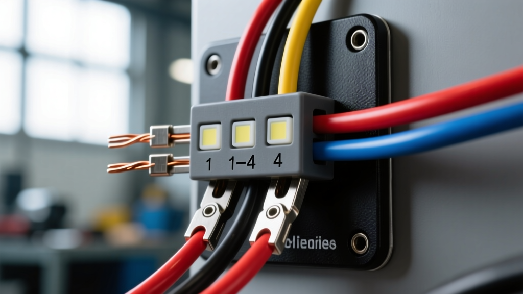
Understanding the 4 Pin LED Wiring Diagram & Pinout
Transitioning a trailer from incandescent bulbs to LED lighting is one of the most reliable upgrades an operator can make. LEDs draw significantly less current, generate minimal heat, and boast a lifespan exceeding 100,000 hours. However, installing an LED harness requires a precise understanding of the 4 pin LED wiring diagram and the unique electrical characteristics of light-emitting diodes. Unlike traditional 1157 incandescent bulbs that act as simple resistive loads, LEDs rely on internal driver circuits and capacitors. This distinction fundamentally alters how you must approach wire gauge selection, grounding, and vehicle-side module integration.
Below is the industry-standard 4-way flat connector pinout, optimized for LED trailer applications according to SAE J2865 and RVIA guidelines.
| Pin / Terminal | Wire Color | Function | Recommended AWG (LED) | Technical Notes |
|---|---|---|---|---|
| 1 (Ground) | White | Chassis Ground | 14 AWG | LED driver boards are highly sensitive to voltage drops. Upgrading the ground from 16 to 14 AWG prevents floating grounds and micro-flickering. |
| 2 (Tail) | Brown | Running / Marker Lights | 16 AWG | Carries continuous low-amperage load (~0.5A total for full LED marker arrays). |
| 3 (Left) | Yellow | Left Turn / Stop | 16 AWG | Pulses high-current inrush to LED capacitors; requires high-strand-count OFC wire. |
| 4 (Right) | Green | Right Turn / Stop | 16 AWG | Ensure dielectric grease is applied to the terminal to prevent galvanic corrosion. |
Tool Requirements for LED Trailer Harnesses
Wiring an LED trailer harness demands more precision than slapping on standard butt connectors. Because LEDs draw less steady-state current, any increase in resistance from a poor crimp or corroded splice will cause a disproportionate voltage drop, leading to premature driver failure. Budget approximately $85 to $150 for the proper tooling if you do not already own them.
- Ratcheting Wire Crimper (AWG 16-14): Do not use cheap plier-style crimpers. A ratcheting crimper ensures a gas-tight connection that prevents oxygen and moisture from wicking into the copper strands. Cost: ~$35.
- Dual-Temperature Heat Gun: Required for activating adhesive-lined heat shrink tubing. You need a low setting (250°F) to position the tubing and a high setting (450°F) to melt the internal polyolefin adhesive. Cost: ~$40.
- Digital Multimeter (DMM) with Duty Cycle/Hz: Essential for diagnosing modern tow vehicles. Standard test lights cannot accurately read Pulse Width Modulation (PWM) signals used by modern Body Control Modules (BCMs). Cost: ~$45.
- Wire Strippers with Micro-Gauge Jaws: LED harness wires often feature thinner insulation. Precision strippers prevent nicking the copper strands, which reduces ampacity. Cost: ~$20.
Material Cost Breakdown: Doing It Right
The most common failure mode in DIY 4 pin LED wiring diagrams is the use of Copper-Clad Aluminum (CCA) wire and standard PVC heat shrink. CCA wire has 30% higher resistance than Oxygen-Free Copper (OFC) and is prone to galvanic corrosion when exposed to road salt. Below is a cost analysis for a professional-grade, 25-foot LED trailer harness build.
| Material Component | Specification | Estimated Cost |
|---|---|---|
| Bonded Trailer Wire (25 ft) | 16 AWG, 4-Conductor, 100% OFC, UV-Jacketed | $22.00 |
| 4-Way Flat Connector (Trailer Side) | Molded rubber boot, heavy-duty copper terminals | $14.00 |
| Adhesive-Lined Heat Shrink Splices | 16-14 AWG, 3:1 Shrink Ratio, Polyolefin (50-pack) | $18.00 |
| PWM Bypass Module / Load Resistors | Required for 2018+ Ford/Ram/GM BCM integration | $35.00 |
| Dielectric Grease & Loom | Silicone-based paste + 1/4 inch split loom (10 ft) | $12.00 |
| Total Estimated Material Cost | Professional-Grade LED Harness Build | $101.00 |
While a budget build using CCA wire and vinyl electrical tape can be completed for under $25, the $100 investment in OFC wire and adhesive heat shrink guarantees a maintenance-free harness for over a decade. The adhesive sealant physically blocks capillary action, preventing water from traveling down the wire jacket into the LED housing.
The PWM Dilemma: Why LEDs Fail on Modern Trucks
When referencing a standard 4 pin LED wiring diagram, most guides ignore the vehicle-side electronics. If you are towing with a modern truck (e.g., 2018+ Ford F-150, RAM 1500, or Silverado), the Body Control Module (BCM) performs a 'bulb check' every time you turn on the lights or press the brake pedal.
The BCM sends a high-frequency, low-duty-cycle Pulse Width Modulation (PWM) signal down the yellow and green wires. An incandescent bulb acts as a simple resistor; even a millisecond pulse generates enough current draw for the BCM to verify continuity. LEDs, however, utilize diodes and capacitors. They do not draw the expected 2.1 amps during the microsecond test pulse. The BCM interprets this low draw as a 'blown bulb' and immediately cuts power to the circuit, resulting in hyper-flashing, dashboard trailer-disconnected warnings, or complete light failure.
The Solution: You must install a PWM bypass module or 50W load resistors on the yellow and green circuits near the vehicle-side connector. A bypass module uses internal relays to draw a dummy load during the BCM test pulse, then switches to clean DC power for the LEDs. This is a non-negotiable step for modern tow vehicles.
Step-by-Step Troubleshooting Matrix
Use this decision tree when your LED trailer lights malfunction after following the 4 pin LED wiring diagram.
| Symptom | Probable Cause | Diagnostic Action & Fix |
|---|---|---|
| LEDs flicker rapidly at idle | Alternator ripple voltage or floating ground. | Check White wire ground. Sand to bare metal, apply dielectric grease, and secure with a star washer. Upgrade ground to 14 AWG. |
| Turn signals hyper-flash | BCM bulb-out detection (PWM rejection). | Install a dedicated LED PWM bypass module at the tow vehicle's 4-pin receptacle. |
| Running lights glow dimly when off | Induced voltage bleed or faulty vehicle relay. | Install a 100-ohm bleeder resistor between the Brown (tail) and White (ground) wires on the trailer side. |
| Left turn activates right marker | Ground loop backfeed. | The trailer is grounding through the hitch ball instead of the White wire. Clean hitch contact points and verify dedicated ground wire continuity. |
Authoritative References & Standards
Proper trailer wiring is governed by strict automotive and recreational vehicle standards. When sourcing materials and designing your 4 pin LED wiring diagram, always adhere to the following guidelines:
- SAE J1128 / J2865: Defines the requirements for low-tension primary cable and trailer connector pinouts. According to SAE International, wire insulation must withstand extreme temperature cycling and abrasion, which is why cross-linked polyethylene (XLPE) or high-grade PVC is mandated over cheap vinyl.
- Curt Manufacturing Wiring Guides: As a leading OEM supplier, Curt's technical documentation on trailer wiring and PWM integration provides vehicle-specific bypass requirements for modern CANBUS networks.
- etrailer.com Technical Help Center: Offers extensive real-world testing on LED load requirements and trailer wiring troubleshooting, confirming the necessity of adhesive-lined heat shrink for long-term moisture resistance.
By investing in the correct tools, utilizing OFC copper wire, and addressing modern PWM signaling, your 4-pin LED trailer harness will outlast the trailer itself. Never compromise on the ground circuit or the splice sealing method; these two factors account for 95% of all premature LED trailer lighting failures.