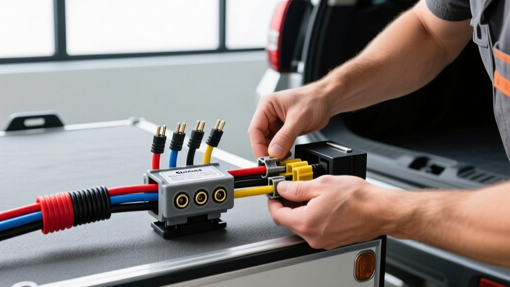
Introduction to the Subaru Outback Towing Electrical System
The Subaru Outback is a highly capable midsize crossover, offering a towing capacity of 2,700 lbs on the standard 2.5L engine and up to 3,500 lbs on the 2.4L Turbo (XT/Onyx) models. However, matching this mechanical capability requires a robust electrical setup. A proper Subaru Outback trailer wiring harness installation is not as simple as splicing into the tail light wires. Modern Outbacks utilize advanced multiplex wiring networks that require specific interface modules to prevent damage to the vehicle's Body Control Module (BCM). This complete diagram walkthrough provides the technical specifications, wire color codes, and step-by-step routing procedures required for a safe, factory-grade 4-pin flat or 7-way RV blade installation.
Pre-Installation: Understanding the Outback's CAN-Bus Multiplex System
Before cutting or tapping any wires, it is critical to understand how the Outback manages its exterior lighting. The vehicle uses a CAN-bus multiplex system where the BCM monitors the current draw and resistance of all lighting circuits. If you use a cheap, splice-in trailer wiring kit, the added electrical load of the trailer's incandescent or LED lights will alter the circuit's resistance. The BCM will interpret this anomaly as a short circuit or a blown bulb, resulting in hyper-flashing, disabled lighting circuits, or a permanently damaged BCM. To bypass this, you must use a powered converter module (often branded as a Modulite). This module uses the vehicle's tail light wires only as low-current signal triggers, while drawing the actual amperage required by the trailer directly from the Outback's battery via a dedicated 12 AWG power wire.
Standard 4-Pin Flat Connector Pinout & Wire Color Chart
The 4-pin flat connector is the standard for lightweight utility trailers and small boat trailers without electric brakes. Below is the industry-standard pinout and AWG specification chart for your Outback harness.
| Pin Position | Wire Color | Function | Minimum AWG Rating | Max Amperage (Per Circuit) |
|---|---|---|---|---|
| 1 (Ground) | White | Chassis Ground | 12 AWG | N/A (Return Path) |
| 2 (Tail) | Brown | Tail / Running Lights | 16 AWG | 7.5A (Incandescent) / 2.0A (LED) |
| 3 (Left) | Yellow | Left Turn & Stop | 16 AWG | 4.2A |
| 4 (Right) | Green | Right Turn & Stop | 16 AWG | 4.2A |
Step-by-Step Harness Routing and Connection Walkthrough
Step 1: Accessing the Rear Hatch Wiring Loom
Begin by opening the rear hatch and removing the interior cargo trim panels. Use a nylon trim removal tool to carefully pop the plastic push-pins securing the left-side cargo panel and the rear sill plate. Once the panel is free, locate the main wiring loom exiting the vehicle body through the rubber grommet on the left side of the cargo area. This loom contains the signal wires for the left and right tail lights. Disconnect the OEM tail light pigtail connectors from the back of the tail light assemblies to prepare for the T-connector integration.
Step 2: Integrating the Powered Modulite Converter
Plug the T-connector harness inline between the OEM vehicle pigtail and the tail light assembly. This ensures a plug-and-play signal connection without stripping wires. Next, route the 12 AWG red power wire forward along the vehicle's undercarriage, following the existing brake and fuel lines. Secure the wire with UV-resistant zip ties every 12 inches. Connect the red wire to the positive battery terminal, but you must install an inline 30A resettable circuit breaker within 18 inches of the battery post to protect against catastrophic shorts. Finally, attach the 12 AWG white ground wire to a bare metal chassis point near the rear bumper. Sand away any paint or undercoating to expose bare steel, secure the ring terminal with a zinc-plated flange nut torqued to 12-15 ft-lbs, and coat the connection heavily with dielectric grease to prevent galvanic corrosion.
Step 3: Routing the 4-Pin Flat Connector
Remove the spare tire from the undercarriage to access the routing path. Feed the 4-pin flat connector down through the existing rubber drain plug in the spare tire well, or route it under the rear bumper cover fascia near the exhaust cutout. Ensure the wiring maintains a minimum clearance of 6 inches from the exhaust heat shield to prevent melting the PVC wire insulation. Store the connector inside the spare tire well when not in use, resting it on top of the tire to prevent it from dragging on the pavement.
Upgrading to a 7-Way RV Blade for Electric Brakes
If you are towing a heavier camper or a car hauler with electric brakes utilizing the Outback XT's full 3,500-lb capacity, a 4-pin flat is insufficient. You will need to install a 4-to-7-way adapter and a proportional brake controller (such as the Tekonsha Prodigy P3). The 7-way RV blade adds three critical circuits:
- Pin 2 (Blue Wire, 10 AWG): Electric Brake Output. This wire runs from the 7-way connector forward to the brake controller mounted under the dash, and then directly to the battery via a 30A breaker.
- Pin 4 (Black Wire, 10 AWG): 12V Auxiliary Power. Used for charging trailer breakaway batteries or powering interior trailer lights. Must be fused at 40A near the battery.
- Pin 7 (Yellow/Red Wire, 14 AWG): Reverse Lights / Backup Solenoid. Tapped into the Outback's reverse light circuit at the rear hatch to disengage trailer hydraulic surge brakes when backing up.
Running 10 AWG wire is mandatory for the brake and auxiliary circuits to prevent voltage drop over the 15+ foot run from the front battery to the rear bumper, ensuring the trailer brakes receive adequate amperage during panic stops.
Real-World Troubleshooting: Common Outback Harness Failures
Even with a meticulous installation, environmental factors and trailer-side issues can cause electrical gremlins. Use this symptom-cause-fix decision tree to diagnose common problems:
- Symptom: Dash indicator hyper-flashes when trailer is connected, but trailer lights work.
Cause: The BCM is detecting a resistance mismatch because a non-powered splice-in harness was used, or the trailer has mixed LED and incandescent bulbs.
Fix: Replace the harness with a powered Modulite converter that isolates the trailer's draw from the BCM. - Symptom: Trailer running lights work, but turn signals immediately blow the vehicle's fuse.
Cause: A dead short in the trailer's yellow or green circuit, usually caused by pinched wires near the tongue hinge or a corroded trailer-side plug.
Fix: Inspect the trailer tongue pivot point for exposed copper. Replace the trailer-side plug and seal with silicone. - Symptom: Trailer lights are dim when the Outback's headlights are turned on.
Cause: Severe voltage drop due to a poor ground connection on the trailer frame, forcing current to backfeed through the hitch ball.
Fix: Upgrade the trailer-side ground wire to 10 AWG, attach it directly to the trailer frame (not the hitch coupler), and sand the frame to bare metal. - Symptom: Brake controller displays 'S.H.' (Short) or 'O.L.' (Overload).
Cause: The 10 AWG blue brake wire is pinched against the chassis, or the trailer brake magnets have failed internally.
Fix: Use a multimeter to test the blue wire for continuity to ground. Inspect the undercarriage routing for zip ties that have rubbed through the wire insulation.
Authoritative References
For further technical validation and vehicle-specific TSBs (Technical Service Bulletins), consult the following automotive electrical resources:
- etrailer's Comprehensive Wiring FAQ - Industry-standard guides for Modulite installations and 7-way pinout schematics.
- Tekonsha Technical Resources - Proportional brake controller wiring diagrams and AWG voltage drop charts.
- Subaru Technical Information System (STIS) - Official OEM wiring diagrams, BCM multiplex network topology, and towing capacity specifications.