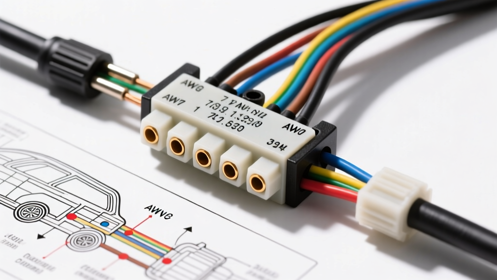
Mastering the Automotive Trailer Wiring Troubleshooting Flow
Electrical faults in towing setups are rarely random; they follow predictable paths of least resistance. When dealing with complex 7-way RV blade configurations, guessing which wire is failing wastes time and risks damaging sensitive vehicle BCMs (Body Control Modules) or trailer brake magnets. This step-by-step diagnostic flow isolates failures in automotive trailer wiring systems, moving from foundational ground checks to advanced voltage drop analysis under load.
Phase 1: Foundational Ground Path Verification
Over 80% of all trailer lighting and brake anomalies stem from a compromised ground circuit. Before probing a single pin on the connector, you must verify the integrity of the white ground wire.
The White Wire Ground Audit
In a standard 7-pin configuration, Pin 1 is the ground. This circuit must utilize a minimum of 10 AWG stranded copper wire to handle the combined return current of the running lights, brake magnets, and 12V auxiliary accessories.
- Visual Check: Inspect the ring terminal where the white wire bonds to the trailer frame. Look for galvanic corrosion (white, powdery aluminum oxide if bolted to an aluminum frame) or rust on steel frames.
- The Backfeed Test: Turn on the tow vehicle's running lights and the left turn signal. If the trailer's left turn signal and running lights illuminate simultaneously at a dim intensity, your ground is completely severed. The current from the brown (running) wire is backfeeding through the yellow (left turn) filament to find a path to ground.
- Dielectric Grease Misapplication: A common failure mode occurs when technicians pack dielectric grease directly onto the mating faces of the plug and socket. This insulates the pins. Grease should only be applied to the rear wire-entry boots to prevent moisture ingress.
Phase 2: 7-Way RV Blade Pinout & Multimeter Testing
If the ground is verified, proceed to static pinout testing. Set your digital multimeter (DMM) to DC Voltage (20V range). Insert the black probe into a known good chassis ground on the tow vehicle, and use the red probe to test the female socket on the vehicle side.
| Pin | Function | Wire Color | Min. AWG | Expected Voltage (Key On) |
|---|---|---|---|---|
| 1 | Ground Return | White | 10 AWG | 0.0V (Continuity to Chassis) |
| 2 | Electric Brakes | Blue | 12 AWG | 0.0V (12V only when brake controller engages) |
| 3 | Tail / Running Lights | Brown | 14 AWG | 12.5V - 14.2V (Headlights On) |
| 4 | Left Turn / Stop | Yellow | 14 AWG | Pulsing 12V (Hazards/Left Turn) |
| 5 | Right Turn / Stop | Green | 14 AWG | Pulsing 12V (Hazards/Right Turn) |
| 6 | 12V Auxiliary / Battery Charge | Black | 10 AWG | 12.5V - 14.2V (Constant or Ignition-Switched) |
| 7 | Reverse Lights | Purple | 14 AWG | 12V (Vehicle in Reverse) |
For deeper reference on standard color codes and adapter configurations, consult the etrailer Comprehensive Wiring FAQ and the Hopkins Manufacturing Wiring Standards.
Phase 3: Symptom-to-Solution Decision Tree
Use this diagnostic decision tree to isolate the specific failure mode based on the driver's reported symptom.
Symptom A: Trailer Brakes Lock Up Immediately Upon Connection
- Step 1: Check the breakaway switch. Is the pin fully inserted? If the pin is pulled or the internal contacts are corroded and shorted, full battery voltage is sent to the brakes.
- Step 2: Inspect the 7-way plug for a short between Pin 2 (Blue/Brakes) and Pin 6 (Black/12V Auxiliary). This frequently happens when the plug is dropped in mud or water, creating a conductive bridge between the terminals.
- Step 3: Verify the brake controller wiring under the dash. If the red (stoplight switch) wire and the blue (output) wire are swapped at the controller pigtail, pressing the vehicle brake pedal sends 12V directly to the trailer brakes instead of triggering the controller's proportional modulation.
Symptom B: Running Lights Flicker or Fail Completely on the Trailer
- Step 1: Perform a voltage drop test on the brown wire. Place one DMM probe on the vehicle's brown pin and the other on the trailer's brown wire at the first junction box. A reading over 0.5V indicates high resistance in the plug or the first 10 feet of harness.
- Step 2: Check for aftermarket LED conversions. If the trailer was upgraded to LED lights without installing load resistors, and the vehicle uses a thermal-style flasher relay or a sensitive BCM multiplexer, the low current draw may cause the vehicle to cut power to the circuit, assuming a short or open fault.
- Step 3: Inspect the trailer junction box (J-box) for water intrusion. The brown wire terminal is often the first to corrode due to its position, leading to intermittent flickering as the trailer flexes over bumps.
Symptom C: Weak or Spongy Electric Brakes at Highway Speeds
- Step 1: Measure wire gauge. Many OEM and budget aftermarket harnesses use 14 AWG wire for the blue brake circuit. Over a 30-foot run to a tandem-axle trailer (4 brake magnets drawing ~3A each, total 12A), 14 AWG wire suffers a severe voltage drop. Upgrade the blue wire from the 7-way plug to the trailer J-box to 10 AWG stranded copper.
- Step 2: Check the ground path for the brake magnets. Each magnet requires an independent ground to the frame, or a dedicated ground wire back to the J-box. Relying on the mounting bolts for ground often leads to high resistance as rust forms between the magnet backing plate and the axle spindle.
- Step 3: Calibrate the brake controller gain. Refer to the CURT Manufacturing Wiring and Controller Guides for specific gain staging procedures based on gross trailer weight (GTW).
Phase 4: Advanced Load Testing & Voltage Drop Analysis
A static multimeter test will not reveal a frayed wire that only fails under high amperage. To complete the troubleshooting flow, you must perform a dynamic load test.
The Incandescent Load Test
Connect a 1156 incandescent bulb (drawing roughly 2.1 Amps at 12V) between the suspect circuit pin and the ground pin on the trailer side. If the circuit is compromised by corrosion or a partial short, the voltage will sag, and the bulb will illuminate dimly. A healthy circuit will drive the bulb to full brightness with no voltage sag.
Calculating Acceptable Voltage Drop
Use the standard voltage drop formula for DC circuits:
VD = (2 x K x I x L) / CM
- K = Resistivity of Copper (12.9 ohms per mil-foot at 77°F)
- I = Current in Amps (e.g., 12A for dual-axle brakes)
- L = One-way length of the wire in feet (e.g., 25 ft)
- CM = Circular Mils of the wire gauge (10 AWG = 10,380 CM; 12 AWG = 6,530 CM; 14 AWG = 4,110 CM)
Example: Running 12A through 25 feet of 14 AWG wire yields a voltage drop of 1.88V. If the tow vehicle alternator is pushing 14.0V, the brake magnets only see 12.12V. While this seems acceptable, under heavy heat (which increases K) and long downhill grades, this voltage deficit translates directly to reduced electromagnetic clamping force on the brake drums, increasing stopping distances. Always oversize the brake and ground circuits to 10 AWG for heavy-duty towing applications.
Summary of Best Practices
Successful automotive trailer wiring troubleshooting relies on a systematic elimination of variables. Always start at the ground, verify pinouts statically, apply the decision tree to isolate the symptom, and finally validate the repair under dynamic electrical load. By adhering to SAE J286 standards and respecting AWG current-carrying limits, you ensure a safe, reliable connection between the tow vehicle and the trailer.