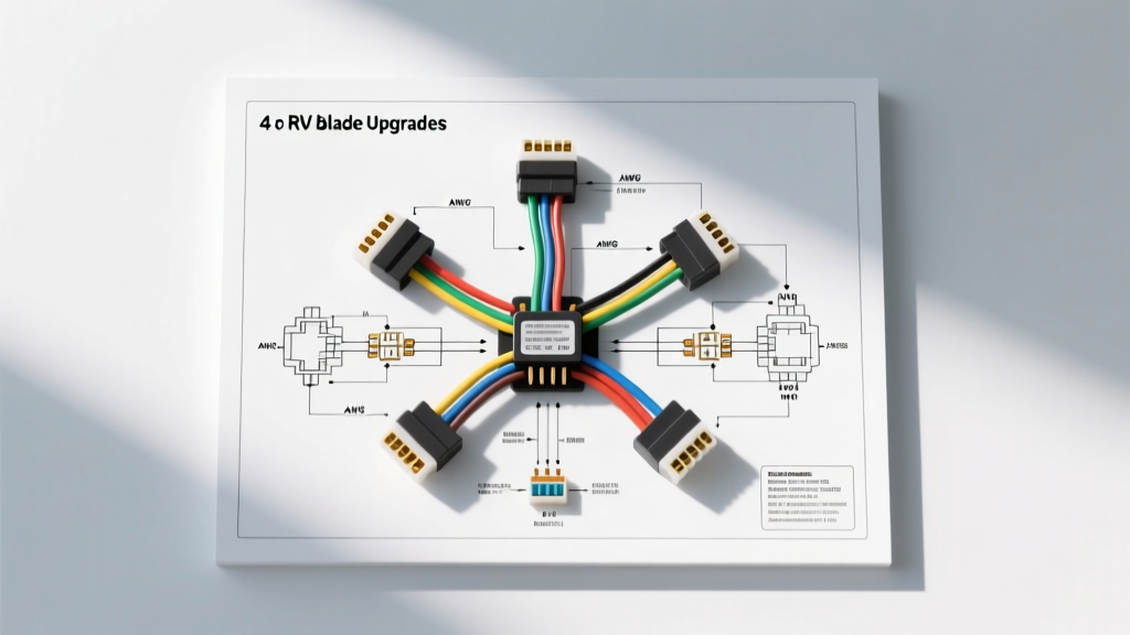
Why Upgrade from a 4-Pin Flat to a 7-Way RV Blade?
For light-duty towing, a standard 4-pin flat connector is sufficient for operating tail lights, brake lights, and turn signals. However, when you upgrade to a heavier travel trailer, horse trailer, or car hauler, the 4-pin system falls critically short. It lacks the circuits required for electric trailer brakes, 12V auxiliary power for charging trailer breakaway batteries, and reverse light lockout for surge brake couplers. Upgrading your tow vehicle to a 7-way RV blade connector is one of the most common and essential modification projects for serious towers.
This comprehensive 7 prong wiring diagram guide provides the exact technical specifications, wire gauge requirements, and routing procedures needed to perform a safe, reliable, and code-compliant 4-pin to 7-way conversion. Unlike generic diagrams, this guide addresses the real-world electrical loads and voltage drop considerations that cause most aftermarket trailer wiring harnesses to fail prematurely.
RVIA Standard vs. SAE J560: Knowing Your 7 Prong Wiring Diagram
Before cutting any wire, it is crucial to understand that not all 7-pin connectors are wired the same. The two dominant standards in North America are the RV Industry Association (RVIA) standard for light/medium-duty RV blades, and the SAE J560 standard for heavy-duty commercial 7-pin round connectors. This guide strictly covers the RVIA 7-Way Flat Blade configuration, which is the universal standard for consumer travel trailers, fifth wheels, and utility trailers equipped with electric brakes.
Standard 7 Prong Wiring Diagram and Pinout Chart
When looking at the face of the vehicle-side 7-way socket (the side the plug inserts into), the pins are arranged in a specific circular pattern. Below is the definitive RVIA pinout chart, including the mandated wire color codes and minimum American Wire Gauge (AWG) requirements to prevent voltage drop over a standard 20-foot harness run.
| Pin Number | Function | Standard Wire Color | Minimum AWG | Circuit Protection |
|---|---|---|---|---|
| Pin 1 | Left Turn / Stop | Yellow | 12 AWG | Vehicle Fuse |
| Pin 2 | Reverse Lights / Aux | Purple | 12 AWG | Vehicle Fuse |
| Pin 3 | Ground (Chassis) | White | 10 AWG | N/A (Direct Ground) |
| Pin 4 | Right Turn / Stop | Green | 12 AWG | Vehicle Fuse |
| Pin 5 | Electric Brakes Output | Blue | 10 AWG | 30A Auto-Reset Breaker |
| Pin 6 | Tail / Running Lights | Brown | 12 AWG | Vehicle Fuse |
| Pin 7 | 12V Battery Charge / Aux | Black | 10 AWG | 40A Auto-Reset Breaker |
Essential Components and Wire Gauge Specifications
A successful modification project relies on marine-grade or automotive-grade materials. Do not use standard hardware store wire; it lacks the cross-linked polyethylene (XLPE) or PVC insulation required to withstand engine bay temperatures and road salt corrosion.
- 7-Way Socket: Pollak PK11898 or equivalent die-cast metal housing socket with spring-loaded terminal pins.
- Wire: SXL or GXL cross-linked automotive primary wire. 10 AWG for high-draw circuits (Ground, Brakes, 12V Aux); 12 AWG for lighting circuits.
- Connectors: Heat-shrink butt splices with polyamide adhesive lining (e.g., Ancor Marine). Never use standard vinyl crimp connectors on exterior harnesses, as they wick moisture via capillary action.
- Circuit Breakers: 30A and 40A auto-reset mechanical circuit breakers (Bussmann or Littelfuse) for the Blue and Black wires.
- Isolation Relay: 40A continuous-duty relay (Pollak PK52301) for the 12V Aux circuit to prevent parasitic battery drain.
Step-by-Step 7-Way Harness Modification Guide
If your vehicle already has a factory or aftermarket 4-pin flat connector, you will use it as the foundation for the lighting circuits, while running new dedicated lines for the brakes and auxiliary power.
Step 1: Tap the Existing 4-Pin Lighting Circuits
Locate the 4-pin harness near the rear bumper. Using wire strippers, carefully tap into the existing wires without cutting the main loom. Splice your new 12 AWG wires as follows:
- Brown (Tail): Splice into the 4-pin Brown wire.
- Yellow (Left): Splice into the 4-pin Yellow wire.
- Green (Right): Splice into the 4-pin Green wire.
- White (Ground): Do NOT splice into the 4-pin white wire. The 4-pin ground is typically 16 AWG and cannot handle the return current for electric brakes. Run a new 10 AWG White wire directly to a clean, bare-metal chassis ground point near the bumper, secured with a star washer and ring terminal.
Step 2: Route the Electric Brake Output (Blue Wire)
Run a continuous, unbroken length of 10 AWG Blue wire from Pin 5 on the 7-way socket, through the firewall grommet, and directly to the output terminal of your aftermarket brake controller (e.g., Tekonsha P3 or Redarc Tow-Pro) mounted under the dash. Install a 30A auto-reset circuit breaker within 18 inches of the brake controller's power source.
Step 3: Integrate the 12V Auxiliary Power (Black Wire)
This is where most DIY upgrades fail. The Black wire (Pin 7) provides a constant 12V charge to the trailer's breakaway battery or interior appliances. If you wire this directly to the tow vehicle's battery, leaving the trailer plugged in overnight will drain your starting battery.
The Expert Fix: Wire the Black 10 AWG wire through a 40A isolation relay. Trigger the relay's coil (terminals 85 and 86) using the Brown (running lights) circuit. This ensures the 12V Aux power is only live when the tow vehicle's headlights are turned on. Route the main power feed from the vehicle battery positive terminal through a 40A auto-reset breaker to the relay's input terminal (30), and out to the 7-way socket via terminal (87).
Step 4: Wire the Reverse Lockout (Purple Wire)
Pin 2 (Purple) is used to activate the reverse lights on the trailer. Crucially, if your trailer has a surge brake coupler with an electric reverse lockout solenoid, this wire disengages the brakes when you back up. Tap into the vehicle's reverse light circuit (usually found at the tail light housing) using a 12 AWG Purple wire and route it to Pin 2.
Advanced Modifications: Brake Controller Signal Integration
For the brake controller to function, it requires a trigger signal indicating that the tow vehicle's brakes are applied. Modern vehicles (2010+) often feature a dedicated blunt-cut tow package pigtail under the dash, or a dedicated OBD-II port module. If your vehicle lacks this, you must tap the stoplight switch at the brake pedal arm.
Warning: Never tap the brake controller trigger wire into the rear brake light wiring harness on vehicles with multiplexed CAN-bus systems or LED tail lights with pulse-width modulation (PWM). This will cause the brake controller to behave erratically or throw a dashboard CEL (Check Engine Light). Always source the trigger signal at the pedal switch or factory tow module. For detailed vehicle-specific tow module locations, consult resources like etrailer's comprehensive wiring FAQ or your vehicle's Haynes service manual.
Real-World Troubleshooting: Common Upgrade Failure Modes
Even with a perfect 7 prong wiring diagram, environmental factors and poor termination can cause faults. Use this diagnostic tree to resolve common issues:
- Symptom: Brake controller displays "OL" (Overload) or "SH" (Short) when trailer is connected.
Cause: A short to ground on the Blue wire, or a severely undersized White ground wire causing current to backfeed through the lighting grounds.
Fix: Disconnect the trailer. Probe the Blue wire at the 7-way socket with a multimeter set to Ohms. It should read infinite resistance (OL). If it reads near 0 Ohms, the Blue wire is pinched or melted against the chassis. Next, verify the 10 AWG White ground has less than 0.2 Ohms of resistance to the vehicle battery negative terminal. - Symptom: Tow vehicle battery is dead in the morning after leaving the trailer plugged in.
Cause: The Black 12V Aux wire was wired directly to the battery without an isolation relay, allowing the trailer's breakaway battery and interior parasitic draws to drain the tow vehicle.
Fix: Install the 40A continuous-duty relay triggered by the Brown running light circuit as detailed in Step 3. - Symptom: Running lights blow the vehicle's fuse immediately upon connection.
Cause: Moisture intrusion inside the trailer-side 7-way plug, or a corroded trailer pigtail causing a short between the Brown wire and the chassis ground.
Fix: Replace the trailer-side plug. Coat all internal socket terminals with dielectric grease (e.g., Nyogel 760G) to prevent galvanic corrosion and water bridging. - Symptom: Trailer brakes lock up aggressively at low speeds or pulse erratically.
Cause: Voltage drop on the Blue wire due to using 12 AWG wire instead of the required 10 AWG, or a poor ground at the brake magnets.
Fix: Measure voltage at the trailer's brake magnet while the controller is set to maximum output. If you read less than 11.5V at the magnet, upgrade the Blue and White wires to 10 AWG or 8 AWG for long trailers.
Final Safety and Torque Specifications
When terminating the wires into the back of the 7-way socket, ensure the set screws are tightened to the manufacturer's specification (typically 15-20 in-lbs). Loose set screws will cause arcing under the high amperage draw of electric brakes, melting the socket housing. Finally, wrap the entire harness loom in split-loom tubing and secure it with UV-resistant zip ties, ensuring a minimum 4-inch droop loop before the connector to prevent tension on the socket terminals during tight turning maneuvers. By adhering strictly to this 7 prong wiring diagram and utilizing heavy-gauge, marine-grade components, your upgraded tow vehicle will deliver safe, reliable performance for years to come.