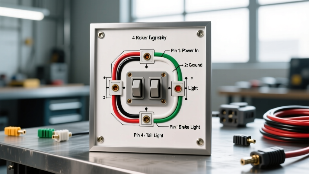
Introduction to 4-Pin Rocker Switches in Trailer Applications
When integrating auxiliary lighting, winch controls, or electric brake manual override systems into a truck or trailer setup, selecting the right control interface is critical for both safety and reliability. The 4 pin rocker switch has become the industry standard for off-road and heavy-duty towing applications. Unlike standard 3-pin SPST (Single Pole Single Throw) switches, a 4-pin configuration separates the main high-amperage load circuit from the internal LED illumination circuit. This independent illumination control prevents battery drain when the main circuit is off and allows the driver to dim or disable the switch backlighting during night driving to preserve night vision.
This complete wiring diagram walkthrough details how to properly wire a 4 pin rocker switch to control an auxiliary trailer LED light bar, tapping power directly from a standard 7-way RV trailer connector while adhering to automotive electrical best practices.
Anatomy of a Standard 4-Pin Illuminated Rocker Switch
Before cutting any wire, it is imperative to understand the terminal layout. While manufacturers like Carling Technologies or Del City Wire may use slightly different physical orientations, the electrical logic for a standard 12V DC SPST illuminated 4 pin rocker switch remains consistent. The switch contains two internal circuits: the main contactor and the LED resistor network.
Terminal Identification and Pinout Chart
Most high-quality automotive rocker switches feature brass or copper-alloy spade terminals. Refer to the table below for the universal pinout configuration, recommended wire colors, and American Wire Gauge (AWG) specifications based on SAE J1128 primary cable standards.
| Pin Number | Terminal Function | Circuit Type | Recommended Wire Color | Min. AWG (20A Max) |
|---|---|---|---|---|
| Pin 1 | Main Power In (Source) | High Current Load | Red (with inline fuse) | 12 AWG |
| Pin 2 | Main Power Out (Load) | High Current Load | Blue | 12 AWG |
| Pin 3 | Illumination Power In (+) | Low Current LED | White or Orange | 18 AWG |
| Pin 4 | Illumination Ground (-) | Low Current LED | Black | 18 AWG |
Complete Wiring Walkthrough: Auxiliary Trailer Light Bar Integration
In this scenario, we are wiring a 4 pin rocker switch mounted in the truck cab to control a 15-amp auxiliary LED light bar mounted on the trailer tongue or rear bumper. Because inductive loads and long wire runs to the trailer can cause voltage spikes and voltage drop, we will use the 4-pin switch to trigger a 30A Bosch-style automotive relay, rather than running the full 15A load directly through the switch contacts. This extends the lifespan of the switch and prevents internal arcing.
Step 1: Tapping Power from the 7-Way RV Connector
Locate the 7-way RV blade connector at the rear of the tow vehicle. According to standard RV wiring configurations, the center pin (often designated as Pin 5 or the 12V Auxiliary Charge pin) provides a constant 12V+ feed directly from the vehicle's battery or auxiliary fuse block.
- Disconnect the negative battery terminal before tapping into the harness.
- Use a T-tap or, preferably, cut the wire and use a sealed heat shrink butt connector to branch off the 12V Aux wire.
- Run a 10 AWG primary power wire from this tap, routed along the frame rail inside a split-loom corrugated tubing, up through the firewall to the cab dash panel.
- Critical: Install a 20A ATC blade fuse holder within 18 inches of the 7-way connector tap to protect the entire downstream circuit.
Step 2: Wiring the 4 Pin Rocker Switch to the Relay
Mount the 4 pin rocker switch into your dash switch panel (standard cutout is typically 1.45" x 0.83"). Wire the switch to the 30A relay located under the hood or behind the dash kick panel.
- Pin 1 (Main Power In): Connect the 10 AWG power wire from the 7-way tap (post-fuse) to Pin 1. If using a relay for the main load, Pin 1 and Pin 2 will only carry the relay coil current (approx. 150mA), but maintaining 12 AWG wire ensures mechanical durability and prevents voltage drop over long cab-to-trailer runs.
- Pin 2 (Main Power Out): Run a 12 AWG wire from Pin 2 to Pin 85 (Relay Coil Input) on the 30A automotive relay.
- Relay Pin 86 (Coil Ground): Ground this pin to a clean, bare-metal chassis point using a ring terminal and a self-tapping star washer to ensure a solid ground bite.
- Relay Pin 30 (Main Source): Connect directly to the vehicle's main 12V battery positive terminal via a dedicated 30A inline fuse.
- Relay Pin 87 (Main Load): Run a 12 AWG wire out to the trailer plug's auxiliary circuit or directly to the LED light bar.
Step 3: Configuring the Independent Illumination Circuit
The true advantage of the 4 pin rocker switch is the ability to control the LED backlight independently of the main load.
- Pin 3 (Illumination +): Splice this 18 AWG wire into the vehicle's headlight switch parking light circuit. This ensures the switch only lights up when the headlights or parking lights are on, preventing daytime battery drain and nighttime glare.
- Pin 4 (Illumination -): Terminate this 18 AWG black wire to a dedicated dash ground bus bar. Do not share this ground with high-current accessories, as ground-loop voltage fluctuations will cause the switch LED to flicker.
Wire Gauge, Voltage Drop, and Environmental Sealing
When wiring trailer accessories, the environment is harsh. Exposure to road salt, moisture, and extreme vibration demands rigorous installation standards. Always use SAE J1128 compliant cross-linked polyethylene (XLPE) insulated wire, which withstands higher under-hood temperatures than standard PVC wire.
For runs exceeding 15 feet from the battery to the trailer accessory, calculate voltage drop using the formula: Voltage Drop = (2 x Length x Current x Wire Resistance per 1000ft) / 1000. If your 15A LED light bar is 25 feet away from the battery, a 12 AWG wire will yield a voltage drop of approximately 1.18V, leaving 10.82V at the load. This is acceptable for most LED drivers, but if you are powering an electric winch solenoid or a trailer-mounted air compressor, you must step up to 10 AWG or 8 AWG wire to prevent relay chatter and component failure.
Furthermore, ensure your 4 pin rocker switch is rated for IP67 or IP68 waterproofing if mounted in an exposed exterior location, such as a truck bed toolbox or an open trailer tongue box. For exterior mounts, use dielectric grease on all spade terminals before connecting, and apply a secondary layer of liquid electrical tape to seal the rear of the switch housing against moisture ingress.
Troubleshooting Common 4-Pin Switch Failures
Even with a perfect diagram, real-world trailer wiring often presents unique failure modes. Use the following symptom-cause-fix matrix to diagnose issues rapidly.
| Symptom | Probable Cause | Diagnostic Fix |
|---|---|---|
| Switch LED illuminates, but accessory does not engage. | Main load circuit open; relay coil not receiving ground; or blown main fuse. | Use a multimeter to test for 12V+ at Pin 2 when switched ON. Check Relay Pin 86 ground continuity. Inspect ATC fuse near the battery. |
| Switch gets physically hot to the touch or smells like melting plastic. | Switch is carrying the full accessory load without a relay, exceeding its 20A continuous rating, or a short-to-ground is causing high amperage draw. | Immediately cut power. Measure accessory amperage with an inline clamp meter. Install a 30A Bosch relay so the switch only handles the <1A coil current. |
| Switch LED flickers or dims when hitting bumps. | Loose ground connection on Pin 4 or a failing crimp on the illumination power splice. | Perform a voltage drop test across the ground wire while wiggling the harness. Replace push-in spade connectors with heat-shrink ring terminals. |
| Accessory works, but switch LED stays on even when vehicle is off. | Pin 3 (Illumination +) is wired to a constant 12V+ source instead of the headlight/parking light circuit. | Move the Pin 3 tap to a circuit that is only hot when the headlight switch is in the 'Park' or 'On' position. |
Summary and Best Practices
Wiring a 4 pin rocker switch for trailer applications requires more than simply connecting power and ground. By isolating the illumination circuit, utilizing relays for heavy inductive loads, and adhering to SAE wire gauge standards, you ensure a robust, fail-safe system. Always secure your wiring with adhesive-lined heat shrink, useDeutsch connectors for any removable trailer-side connections, and verify all circuits with a digital multimeter before applying full load. For further reference on primary cable standards and connector specifications, consult the SAE J1128 documentation and verify your specific vehicle's 7-way pinout against the manufacturer's towing guide.