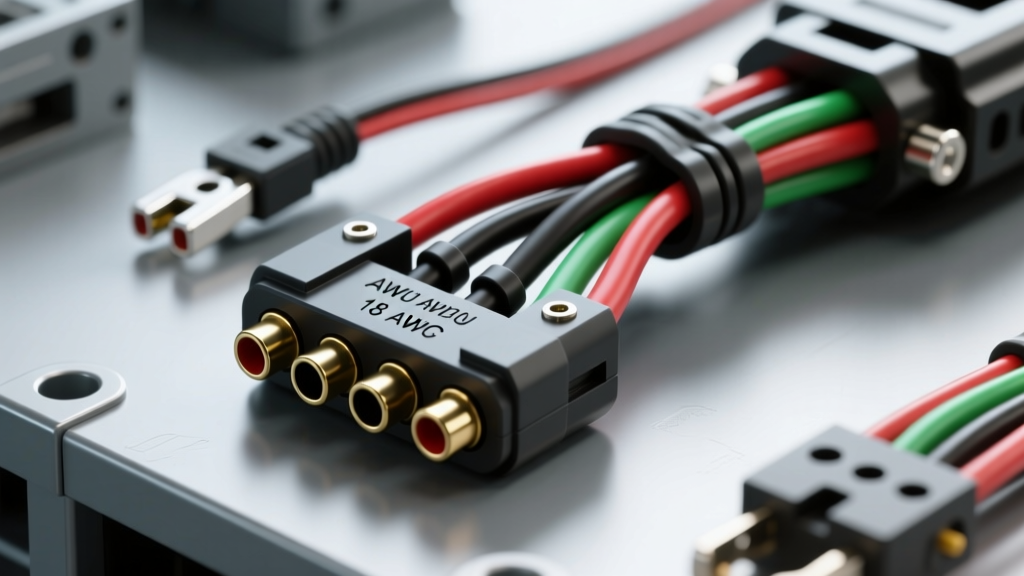
The Anatomy of a Standard 4 Pin Car Connector
The 4 pin car connector (often referred to as a 4-way flat) is the most ubiquitous light-duty towing interface in North America. Standardized by the RV Industry Association (RVIA) and aligned with FMVSS 108 lighting requirements, this connector handles the essential lighting functions for small utility trailers, boat trailers, and lightweight campers. However, its simplicity is deceptive. A vast majority of trailer lighting failures, blown vehicle fuses, and even electrical fires stem from improper installation and a fundamental misunderstanding of modern vehicle electrical systems.
Before splicing into your vehicle's harness, you must understand the standardized pinout. Unlike heavier 7-way blade connectors that handle 12V auxiliary power and electric brake controllers, the 4 pin car connector is strictly dedicated to basic illumination and signaling.
Standard 4-Way Flat Pinout & AWG Specifications
| Pin Position | Wire Color | Function | Recommended AWG |
|---|---|---|---|
| 1 (Ground) | White | Chassis Ground Return | 12 to 14 AWG |
| 2 (Running) | Brown | Tail Lights, License Plate, Side Markers | 16 AWG |
| 3 (Left) | Yellow | Left Turn Signal & Stop Light | 16 AWG |
| 4 (Right) | Green | Right Turn Signal & Stop Light | 16 AWG |
Note: While 16 AWG is standard for lighting circuits, upgrading the White ground wire to 12 AWG is highly recommended for trailers with extensive LED marker arrays to prevent voltage drop.
5 Critical Wiring Mistakes (And How to Fix Them)
When installing a 4 pin car connector, both professional mechanics and DIY enthusiasts frequently fall into the same traps. Below are the most common mistakes that compromise safety and functionality.
1. Frying the BCM on Modern CAN-Bus Vehicles
The Mistake: Splicing a standard passive T-connector directly into the tail light wires of a modern vehicle (typically 2010 and newer). Modern vehicles use multiplexed wiring, Pulse Width Modulation (PWM), and a centralized Body Control Module (BCM) to monitor bulb resistance. If you draw trailer current directly through the vehicle's BCM circuit, the module will detect an abnormal resistance spike, trigger a 'bulb out' dashboard warning, and potentially shut down the entire lighting circuit or fry the BCM transistor.
The Fix: You must use a powered converter module (such as the Tekonsha 119190KIT or Curt 56282). These modules draw heavy current directly from the vehicle's battery via a dedicated 12V power wire and use the vehicle's tail light wires merely as low-current signal triggers. According to the etrailer.com Wiring FAQ, using a powered bypass module is mandatory for any vehicle with CAN-bus or PWM lighting systems.
2. The 'Chassis Ground' Fallacy
The Mistake: Assuming the trailer hitch ball and receiver provide a sufficient ground return path, and therefore neglecting to run the White ground wire to the trailer frame.
The Fix: The hitch ball is coated in paint, grease, and rust, creating immense electrical resistance. The White wire on the 4 pin car connector MUST be grounded to a clean, bare metal surface on the vehicle chassis using a ring terminal and self-tapping screw. Similarly, the trailer side must have its own dedicated White wire grounded directly to the bare steel tongue. Never rely on the physical coupling for ground continuity.
3. Undersized Ground Wires and Voltage Drop
The Mistake: Using the factory 18 AWG white wire included in cheap replacement plugs for a trailer equipped with 20+ LED clearance lights and dual brake lights.
The Fix: LEDs draw less current than incandescent bulbs, but a high volume of them still creates cumulative resistance over a 25-foot trailer length. If the ground wire is undersized, voltage drops, resulting in dim lights or 'ghost lighting' (where applying the brakes causes the running lights to turn off). Upgrade the ground circuit to 12 AWG stranded copper wire to ensure a zero-resistance return path.
4. Soldering High-Vibration Strain Relief Points
The Mistake: Soldering the wire connections directly behind the rubber strain relief of the 4 pin car connector plug.
The Fix: Solder creates a rigid, brittle joint. The area immediately behind the connector plug is a high-vibration, high-flex zone. Over time, the rigid solder joint will fatigue, crack, and short out against adjacent pins. Instead, use adhesive-lined marine-grade heat shrink crimp connectors. The crimp maintains mechanical flexibility, while the heat shrink seals out moisture and prevents corrosion.
5. Mixing Up Yellow and Green (Left vs. Right)
The Mistake: Reversing the Yellow and Green wires at the trailer junction box. Because the physical plug is symmetrical, it is easy to flip the orientation and swap the left and right turn signals without realizing it until you are on the road.
The Fix: Always verify the pinout on the vehicle side with a digital multimeter or a dedicated 4-way circuit tester before wiring the trailer side. Remember the mnemonic: 'Green is Go' (Right side, passenger side in US/Canada), and Yellow is Left (Driver side).
Troubleshooting Decision Tree: Ghost Lighting & Backfeed
One of the most alarming symptoms of a poorly wired 4 pin car connector is 'backfeed' or 'ghost lighting'—where activating one circuit unintentionally illuminates another. Use this decision tree to diagnose the fault:
- Symptom: Pressing the brake pedal causes the trailer running lights (Brown) to dim or turn off, while the brake lights illuminate.
- Cause: Severe ground deficiency. The current from the brake circuit cannot find a path through the White ground wire, so it backfeeds through the Brown running light filament to find a ground through the vehicle's tail light circuit.
- Fix: Clean the trailer frame ground point to bare metal, sand away any rust, and apply dielectric grease to the terminal.
- Symptom: Left turn signal (Yellow) illuminates the Right turn signal (Green) faintly.
- Cause: Corrosion inside the 4 pin car connector plug causing a micro-short between Pin 3 and Pin 4, or melted plastic housing due to a previous short circuit.
- Fix: Inspect the male and female plug faces. If the rubber divider is compromised or pins are blackened, cut off the plug and install a new molded 4-way flat connector.
Severe Safety Warnings & Fire Hazards
Working with automotive electrical systems carries inherent fire and safety risks. Adhere strictly to these warnings when configuring your 4 pin car connector:
The 18-Inch Fuse Rule
When installing a powered converter module for your 4 pin car connector, the 12V power wire routed to the vehicle battery MUST have an inline ATO/ATC blade fuse holder installed within 18 inches of the battery's positive terminal. If a wire chafes against the chassis before the fuse, it creates a dead short that can ignite the wiring harness and destroy the vehicle. The CURT Manufacturing Wiring Guide strictly mandates this proximity for all powered modules.
Never Tap into 12V Accessory Circuits for Running Lights
Some installers attempt to bypass the Brown (running light) wire by tapping into a 12V accessory or cigarette lighter circuit to power trailer markers. This is a severe violation of FMCSA Title 49 Part 393.9 lighting regulations. Trailer running lights must only illuminate when the tow vehicle's headlights or parking lights are active. Wiring them to a constant 12V source will drain your vehicle battery overnight and blind oncoming drivers during daylight hours.
Dielectric Grease is Mandatory
The 4-way flat connector is highly exposed to road spray, salt, and humidity. Omitting dielectric grease on the pins guarantees galvanic corrosion within a single winter season. Corrosion increases resistance, which generates heat. In extreme cases, the heat generated by a corroded Brown (running light) pin can melt the plastic connector housing, fusing the pins together and causing a catastrophic short circuit. Always pack the female connector cavity with silicone dielectric grease before mating the plugs.
Conclusion
Properly wiring a 4 pin car connector requires more than just matching colors; it demands an understanding of modern vehicle electronics, voltage drop calculations, and environmental sealing. By avoiding direct CAN-bus splicing, ensuring robust grounding, and utilizing proper marine-grade crimping techniques, you will guarantee a safe, reliable, and legally compliant towing setup for years to come.