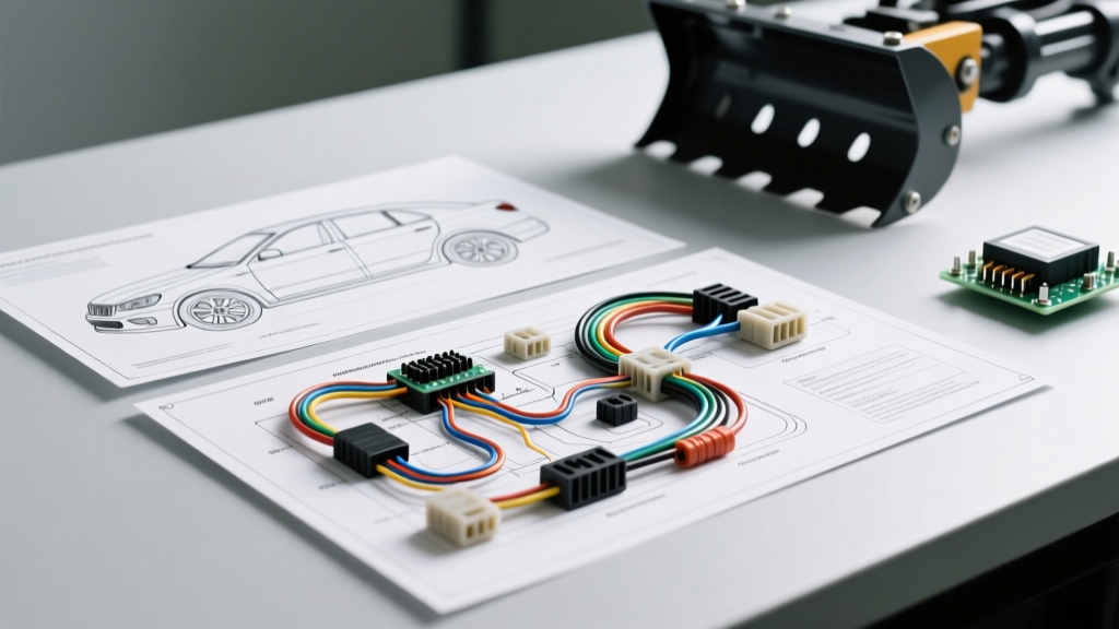
Why Misreading Western Plow Wiring Diagrams Destroys Truck Electrical Systems
Western plow wiring diagrams are the essential blueprint for surviving harsh winter operations, but misinterpreting a schematic on an UltraMount or FleetFlex system is a fast track to melted harnesses, blown Body Control Modules (BCMs), and stranded trucks. Modern work trucks are no longer simple mechanical beasts; they are rolling networks of CAN-bus data lines, shunt sensors, and multiplexed power distribution. When installers and DIYers rely on outdated assumptions rather than the specific Western plow wiring diagrams for their exact chassis and plow model, the results are often catastrophic.
As an automotive electrical specialist, I have diagnosed hundreds of snowplow-related electrical failures. The vast majority do not stem from defective plow components, but from fundamental installation errors and a disregard for safety protocols. Below is a deep-dive audit of the most common wiring mistakes made when installing Western 3-plug systems, alongside the critical safety warnings you must heed before stripping your first wire.
Mistake #1: The 'Chassis Ground' Shortcut (And Why It Fails)
The most pervasive error when reading Western plow wiring diagrams is ignoring the explicit instruction to route the main 2 AWG black ground cable directly to the vehicle's negative battery terminal. Many installers take the 'chassis ground' shortcut, bolting the ground cable to a nearby frame rail or engine block to save time and wire.
The Modern Truck Alternator Shunt Problem
On older trucks (pre-2015), a clean chassis ground might suffice. However, modern heavy-duty trucks—such as the 2020+ Chevrolet Silverado 2500HD with dual alternators or the Ford F-350 Super Duty—utilize Battery Current Sensors (shunts) located directly on the negative battery post. The BCM uses this shunt to monitor exact amperage draw to manage the alternator's output and regulate Auto Start/Stop systems. If you ground your plow to the frame, the massive 100A+ draw of the plow pump motor bypasses the shunt. The BCM will not register the draw, leading to severe undercharging, battery sulfation, and eventually a dead truck in the middle of a snowstorm.
The Fix: Always follow the diagram's ground routing. Use SAE J1127 compliant 2 AWG (or 1/0 AWG for long-wheelbase trucks) stranded copper wire. Route it directly to the negative battery post, ensuring the connection is torqued to manufacturer specifications and coated with a non-hardening dielectric compound.
Mistake #2: Undersizing the Main Power Feed and Skipping the Mega Fuse
Western schematics clearly dictate the use of a 150-Amp Mega Fuse within 18 inches of the positive battery connection, alongside specific AWG requirements for the red power cable. A frequent mistake is substituting the required 2 AWG wire with 4 AWG or 6 AWG wire because 'it was lying around the shop.' Furthermore, some installers bypass the Mega Fuse, relying on the truck's factory under-hood fuse block.
Voltage Drop and Inductive Heat
A Western hydraulic pump motor can draw upwards of 150 amps during startup (stall current) and 40-60 amps during continuous operation. According to SAE J1128 standards for low-tension primary cable, pushing 150 amps through 15 feet of 4 AWG wire results in a voltage drop exceeding 1.5 volts. This voltage drop starves the pump motor, causing it to run hotter, draw even more amperage, and ultimately trip the controller's thermal overload protection.
Skipping the 150A Mega Fuse is a fire hazard. The solenoid can weld itself shut in the 'closed' position during a high-amperage spike. If the solenoid welds closed and the controller fails, the pump motor will run continuously until the wires melt and ignite the surrounding harness tape. The 150A Mega Fuse is your only fail-safe against a harness fire.
Mistake #3: 13-Pin Lighting Connector Pinout Confusion
Western's 3-plug system typically utilizes a 2-pin power plug, a control plug, and a 13-pin lighting plug. The 13-pin lighting connector is frequently confused with standard RV or trailer wiring, leading installers to wire the pins based on memory rather than the specific Western diagram. Swapping the tail/marker circuit with the stop/turn circuits will cause the plow lights to behave erratically and can backfeed voltage into the truck's lighting control module, blowing internal solid-state relays.
| Pin Number | Wire Color (Typical) | Circuit Function | Common Failure Mode if Swapped |
|---|---|---|---|
| 1 | Yellow | Left Turn / Stop | Hyper-flashing, BCM fault code |
| 2 | White | Chassis Ground | Complete lighting failure, backfeed |
| 3 | Brown | Tail / Marker Lights | Markers blow when brakes applied |
| 4 | Green | Right Turn / Stop | Hazards trigger wipers or radio |
| 5 | Black | Backup Lights | Reverse camera shorts out |
| 6 | Red | Auxiliary / High Beam | High beams blind oncoming traffic |
| 7 | Blue | Right Stop (Isolated) | Fused circuit blows instantly |
Note: Always verify the exact pinout against your specific Western harness part number (e.g., 29047 or 28054), as FleetFlex multiplex systems may utilize data pins on the higher pin numbers.
Mistake #4: Using the Wrong Solenoid Type and Ignoring Coil Suppression
The solenoid is the heart of the plow's power delivery. Western systems require an intermittent-duty solenoid (often a Trombetta or White-Rodgers model rated for high inrush currents). A common mistake is replacing a failed OEM solenoid with a cheaper continuous-duty solenoid from an auto parts store. Continuous-duty solenoids have higher coil resistance and lower magnetic pull; they will overheat and fail to engage the pump motor under the extreme vibration and cold of a snowplow environment.
Furthermore, installers often fail to install an arc suppression resistor or flyback diode across the solenoid coil terminals. When the joystick is released and the magnetic field collapses, it sends an inductive voltage spike (sometimes exceeding 100V) back down the 12 AWG trigger wire. Without suppression, this spike will fry the internal PCB of your Western joystick controller or the truck's upfitter switch module.
Mistake #5: Splicing Multiplex Data Lines with Solder and Tape
Newer Western FleetFlex systems utilize multiplexed data lines to communicate between the joystick, the isolation module, and the plow-mounted Grid-Loc module. These data lines carry low-voltage, high-frequency CAN-bus signals. A critical mistake is repairing a broken data wire using standard solder and heat-shrink tubing, or worse, twist-on wire connectors.
Soldered splices create rigid points that fracture under engine vibration. More importantly, improper splicing alters the impedance of the twisted-pair data cable, causing signal reflection and packet loss. This manifests as 'ghosting'—where the plow randomly drops angles or the controller displays a phantom 'Code 11' communication error. Data lines must only be repaired using sealed Deutsch DT connectors or by replacing the entire harness assembly.
Essential Safety Warnings Before You Crimp
Working on modern truck electrical systems with high-amperage plow accessories carries severe risks. Adhere to these safety protocols before beginning any installation or troubleshooting based on Western plow wiring diagrams:
- Airbag Clock Spring Routing: Never route plow control harnesses through the steering column shroud without verifying clearance. Pinching the yellow SRS (Supplemental Restraint System) airbag loom against the plow joystick mount can cause a short circuit, deploying the airbag or disabling the entire safety system.
- Battery Disconnect Sequence: Always disconnect the negative battery terminal first, and reconnect it last. This prevents the negative terminal from arcing against the chassis if your wrench slips while loosening the positive terminal.
- Dielectric Grease Selection: Do not use standard automotive silicone dielectric grease on Western multiplex connectors. Standard silicone can cause certain plastics to swell over time, compromising the weather-seal. Use a specialized electrical contact grease like Nyogel 760G, which is formulated for sensitive multi-pin data connectors.
- Torque Specifications: Hand-tightening solenoid terminal nuts leads to micro-arcing and melted studs. Use a torque wrench set to 120 in-lbs (10 ft-lbs) for standard 5/16-inch solenoid studs to ensure a gas-tight, low-resistance connection.
Conclusion: Respect the Schematic
Western plow wiring diagrams are not mere suggestions; they are engineered solutions designed to integrate high-draw hydraulic accessories with sensitive modern vehicle networks. By avoiding chassis-ground shortcuts, properly sizing your AWG cables, respecting the 13-pin lighting pinouts, and utilizing correct solenoid suppression, you ensure your plow system operates reliably through the harshest winter conditions. Always consult the official Western Plows literature library for the exact schematic matching your truck's make, model, and year before cutting a single zip-tie.