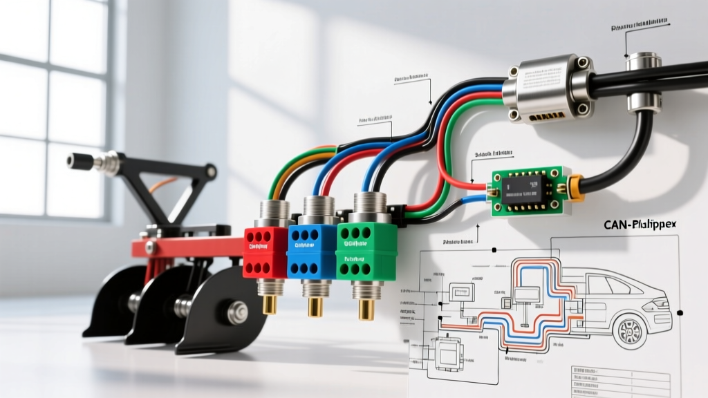
Introduction to Fisher Multiplex Architecture
Modern Fisher snow plow systems, specifically those utilizing the Minute Mount 2 and EZ-V platforms, rely on the advanced Multiplex 2 and Multiplex 3 wiring architectures. Unlike legacy relay-based isolation modules that required heavy-gauge copper runs for every individual lighting circuit, the Fisher Multiplex system utilizes a localized solid-state Headlamp Multiplex Module (HMM) on the plow side and a Vehicle Multiplex Module (VMM) on the truck side. These nodes communicate via a high-speed Controller Area Network (CAN-bus) data link, drastically reducing the physical wire count, minimizing voltage drop, and enabling sophisticated onboard diagnostics.
For advanced automotive electrical technicians, interpreting a Fisher plow wiring diagram requires moving beyond simple continuity testing. You must understand CAN-bus termination resistance, pulse-width modulation (PWM) headlamp switching, and solenoid flyback suppression. This technical deep dive dissects the standard Fisher 3-plug configuration (11-pin lighting, 4-pin power, and 3-pin control), providing actionable diagnostic data, AWG specifications, and oscilloscope benchmarks required to troubleshoot complex electrical faults in extreme winter environments.
11-Pin Lighting Harness Pinout & SAE Standards
The 11-pin connector handles all plow-side lighting functions. While older Fisher systems passed high-current headlamp power directly through the connector, the Multiplex system uses these pins to send low-current logic signals and switched power to the HMM, which then drives the plow lamps. The wire colors and gauges adhere to SAE J1128 Low Tension Primary Cable Standards for durability and voltage drop mitigation.
| Pin | Function | Wire Color | AWG | Multiplex Signal Type |
|---|---|---|---|---|
| 1 | Chassis Ground | Black | 12 | Common Return |
| 2 | Left Turn / Stop | Yellow | 14 | Logic / PWM |
| 3 | Right Turn / Stop | Green | 14 | Logic / PWM |
| 4 | Tail / Marker | Brown | 14 | Logic / PWM |
| 5 | High Beam Trigger | Blue | 14 | Multiplex Data |
| 6 | Low Beam Trigger | White | 14 | Multiplex Data |
| 7 | Auxiliary Ground | Black | 12 | Common Return |
| 8 | Auxiliary / Backup | Purple | 14 | Switched 12V |
| 9 | Plow Lamp Power Feed | Red | 10 | Battery + (Fused) |
| 10 | Daytime Running (DRL) | Orange | 14 | Logic / PWM |
| 11 | Park Lamp | Dark Green | 14 | Logic / PWM |
Diagnostic Note: If the plow marker lights illuminate but the headlamps fail to switch, verify Pin 9 (Red, 10 AWG). The HMM requires a dedicated high-amperage feed to power the sealed beam or LED plow lamps. A corroded Pin 9 will result in a logic-level voltage presence (12V open-circuit) that collapses to under 4V when the HMM attempts to draw 15+ amps for the headlamps.
4-Pin Power Circuit & Solenoid Specifications
The 4-pin power connector is the backbone of the hydraulic pump motor circuit and the main system ground. It utilizes heavy-gauge cabling to handle the massive inrush current (often exceeding 150 amps) required by the Fisher hydraulic power unit during cold-weather operation.
- Pin A (Red, 2 AWG): Direct battery positive feed from the truck-side solenoid to the plow motor.
- Pin B (Black, 2 AWG): Main chassis ground return to the truck battery negative.
- Pin C (Red/White, 14 AWG): Solenoid coil trigger signal from the VMM.
- Pin D (Black/White, 14 AWG): Multiplex ground reference for the solenoid trigger circuit.
Solenoid Coil & Flyback Diode Testing
Fisher utilizes continuous-duty or heavy intermittent Trombetta-style solenoids. The coil resistance should measure between 4.5 and 6.0 ohms at room temperature. However, the most critical and frequently overlooked component in the Fisher Engineering Technical Literature is the internal flyback suppression diode. When the VMM removes power from the solenoid coil, the collapsing magnetic field generates a high-voltage reverse spike (inductive kickback). If the internal diode is open, this spike will instantly fry the solid-state drivers inside the truck-side VMM.
To test the diode, set your digital multimeter (DMM) to the diode test function. Place the red lead on the solenoid ground terminal and the black lead on the trigger terminal. You should read a forward voltage drop of approximately 0.4V to 0.6V. Reversing the leads should yield an 'OL' (open loop) reading. If you read a short (0.0V) or open in both directions, replace the solenoid immediately before installing a new VMM.
3-Pin Control Harness & CAN-Bus Diagnostics
The 3-pin connector carries the CAN-bus data link and the shield ground between the truck-side controller, the VMM, and the plow-side HMM. This is where advanced diagnostics separate parts-changers from true electrical technicians.
- Pin 1 (Green): CAN-High
- Pin 2 (Yellow): CAN-Low
- Pin 3 (Black/Bare): Shield / Signal Ground
Oscilloscope Benchmarks for Multiplex Data
According to ASE A6 Electrical/Electronic Systems diagnostic protocols, relying solely on a DMM for CAN-bus testing is insufficient due to the rapid switching speeds of the data packets. Connect a dual-channel oscilloscope to Pins 1 and 2. With the system awake and the controller actively commanding a plow movement, you should observe the following differential signals:
- CAN-High (Recessive): ~2.5V | (Dominant): ~3.5V
- CAN-Low (Recessive): ~2.5V | (Dominant): ~1.5V
The signals should mirror each other perfectly across the 2.5V baseline. If the CAN-Low signal is pulled flat to 0V, you have a short-to-ground on the yellow wire, often caused by the harness chafing against the Fisher Minute Mount 2 lifting frame. If both lines sit at a steady 2.5V with no square-wave modulation, the VMM has entered a sleep state or has lost its ignition-switched wake-up signal.
Termination Resistance & Network Faults
The Fisher Multiplex CAN-bus requires proper termination to prevent signal reflection and data corruption. The network utilizes two 120-ohm termination resistors—one located inside the VMM and one inside the HMM. With the truck ignition off and the plow disconnected, measure the resistance across the truck-side 3-pin pigtail (Pins 1 and 2). You should read exactly 120 ohms, indicating the VMM resistor is intact.
When the plow is connected, the two 120-ohm resistors are placed in parallel, and a multimeter read across the data lines should yield exactly 60 ohms. A reading of 120 ohms while connected indicates an open circuit in the plow-side harness or a failed HMM internal resistor. A reading near 0 ohms indicates the data lines are shorted together, commonly due to water intrusion and galvanic corrosion inside the 3-pin weather-pack connector.
Environmental Failure Modes & Harness Routing
Snow plow wiring operates in the most hostile electrical environment on a vehicle: a combination of road salt, extreme thermal cycling, high-pressure washes, and constant mechanical vibration. The most prevalent failure mode in Fisher 3-plug systems is fretting corrosion at the truck-side bulkhead connectors.
Micro-movements between the male and female terminals break down the tin or gold plating, leading to oxidation. This increases contact resistance, which generates heat and causes the plastic connector housing to melt or deform. To prevent this, all Fisher Multiplex connectors must be packed with a high-dielectric, water-repellent silicone grease (such as Nyogel 760G) during every seasonal installation. Never use standard chassis grease or petroleum jelly, as these can degrade the EPDM rubber weather seals and cause capillary action, wicking saltwater directly into the VMM or HMM nodes.
Furthermore, ensure the 2 AWG power cables are routed with a minimum bend radius of 1.5 inches. Sharp bends in cold weather (below 0°F) cause the copper stranding to work-harden and snap internally, leading to intermittent high-current failures that will only manifest when the hydraulic pump is under maximum load, such as when lifting a fully loaded moldboard.