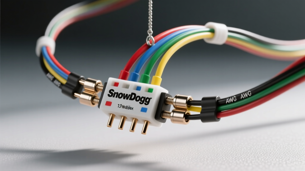
Introduction to SnowDogg Multiplex Architecture
The evolution of the SnowDogg plow wiring harness marks a significant departure from legacy discrete-relay systems. Modern SnowDogg plows, engineered by Buyers Products, utilize a sophisticated 13-pin multiplex architecture. This system replaces heavy, multi-wire looms with a localized Controller Area Network (CAN) bus and Pulse Width Modulation (PWM) signaling. For the advanced automotive electrical technician, understanding this harness requires moving beyond simple continuity testing and into the realm of digital signal tracing, magnetic latch valve logic, and high-current voltage drop analysis.
Unlike older 11-pin or 12-pin setups that routed raw 12V+ current directly from the cab controller to the hydraulic valves, the modern SnowDogg 13-pin harness sends low-current data signals to a smart node mounted on the plow A-frame. This node then distributes high-current power locally. This design drastically reduces voltage drop, minimizes copper weight, and allows for precise current-limiting diagnostics. Below is an advanced technical breakdown of the harness topology, pinout matrix, and diagnostic protocols required to service these systems effectively.
13-Pin Multiplex Connector Pinout Matrix
The core interface between the truck-side isolator module and the plow-side smart node is the 13-pin environmental connector. Proper pin identification is critical, as misalignment or cross-pinning during harness replacement will instantly destroy the CAN-bus transceivers. The following matrix details the Gen 3 SnowDogg multiplex pinout, including wire gauge and functional assignments.
| Pin | Wire Color | AWG | Function / Signal Type | Nominal Voltage |
|---|---|---|---|---|
| 1 | Black | 8 | Main System Ground (Chassis/Battery Neg) | 0.0V |
| 2 | Red | 8 | 12V+ Constant Battery Feed (Post-Solenoid) | 12.6V - 14.4V |
| 3 | Brown | 16 | Left Turn / Marker Lamp Feed | 12V+ (Switched) |
| 4 | Green | 16 | Right Turn / Marker Lamp Feed | 12V+ (Switched) |
| 5 | Black/White | 14 | Headlight Common Ground | 0.0V |
| 6 | Blue | 14 | Headlight High Beam Feed | 12V+ (Switched) |
| 7 | White | 14 | Headlight Low Beam Feed | 12V+ (Switched) |
| 8 | Yellow (Twisted) | 18 | CAN-High (Data Bus +) | 2.5V - 3.5V (Idle) |
| 9 | Green (Twisted) | 18 | CAN-Low (Data Bus -) | 1.5V - 2.5V (Idle) |
| 10 | Pink | 16 | Ignition Switched Wake-Up Signal | 12V+ (Key ON) |
| 11 | Orange | N/A | Reserved / Aux Lighting PWM | 0-12V PWM |
| 12 | Purple | N/A | Reserved / Diagnostic Trigger | Logic Level |
| 13 | Grey | 16 | Plow Attach / Float Switch Return | 5V Reference |
Note: Pins 11 and 12 are often populated in V-Box spreader integrations but remain reserved on standard straight-blade SnowDogg harnesses. Always verify against the specific Buyers Products schematic for your serial number range.
Power Feed, Solenoid, and Ground Routing Specifications
The high-current side of the SnowDogg plow wiring harness relies on a continuous-duty solenoid to isolate the plow's electrical load from the truck's sensitive ECM and CAN networks when the plow is not in use. Improper routing or undersized cabling in this segment is the leading cause of sluggish hydraulic performance and low-voltage fault codes.
Main Battery Feed and Solenoid Topology
The main power feed must utilize 2 AWG stranded copper wire (compliant with SAE J1128 specifications for low-tension primary cable). This cable routes from the truck battery positive terminal, through a 150A MEGA fuse (mounted within 18 inches of the battery), to the input stud of the continuous-duty solenoid.
- Solenoid Type: Trombetta or White-Rodgers style, 12V DC, continuous duty, minimum 150A inrush / 100A holding capacity.
- Activation Circuit: The solenoid coil is triggered by the isolator module via a 16 AWG blue wire, which receives a 12V+ signal only when the ignition is ON and the controller is powered up.
- Terminal Torque Specs: Battery and solenoid lug nuts must be torqued to exactly 110 in-lbs (9 ft-lbs). Over-torquing will snap the solenoid stud; under-torquing will cause micro-arcing, leading to localized melting and catastrophic voltage drop.
Grounding Architecture
SnowDogg systems demand a dedicated, isolated ground path. Do not rely on the plow hitch or A-frame pivot points for electrical grounding. The 8 AWG black ground wire (Pin 1) must terminate directly to the truck's chassis ground bus or battery negative terminal. The connection point must be sanded to bare metal, treated with an anti-corrosive compound, and secured with a Grade 8 bolt torqued to 25 ft-lbs.
Hydraulic Valve Coil Specifications & PWM Logic
The plow-side smart node controls the hydraulic manifold valves using Pulse Width Modulation (PWM). This allows the node to monitor the exact current draw of each coil, providing real-time short-circuit and open-circuit protection. When diagnosing a non-responsive valve, technicians must measure the coil resistance and verify the PWM signal rather than simply checking for 12V.
Magnetic Latch Valve Diagnostics
SnowDogg utilizes magnetic latch (or proportional drop) valves for angle and lift functions. The internal coil specifications are highly specific:
- Coil Resistance: 2.5 to 4.0 Ohms at 68°F (20°C).
- Inrush Current: 4.5A to 5.5A (Duration: 50-100ms).
- Holding Current (PWM): 0.8A to 1.2A (Duty cycle drops to maintain latch without overheating the coil).
If a valve coil reads below 2.0 Ohms, the internal winding insulation has degraded, and the smart node will actively throw a 'Valve Short' fault and disable that specific circuit to protect the MOSFET drivers. If the resistance is infinite, the internal thermal fuse has blown, requiring complete cartridge replacement.
Advanced Diagnostics: Oscilloscope & Voltage Drop
Because the SnowDogg harness relies on CAN-bus communication between the cab joystick and the A-frame node, a standard Digital Multimeter (DMM) is often insufficient for diagnosing intermittent communication faults (e.g., the plow randomly dropping offline or joystick LEDs flashing erratically).
CAN-Bus Signal Tracing
To verify the integrity of Pins 8 (CAN-H) and 9 (CAN-L), connect a dual-channel automotive oscilloscope. Set the voltage scale to 5V/div and the timebase to 10ms/div.
- CAN-High (Pin 8): Should idle at approximately 2.5V and spike to 3.5V during dominant bit transmission.
- CAN-Low (Pin 9): Should idle at approximately 2.5V and drop to 1.5V during dominant bit transmission.
- Differential Voltage: The difference between CAN-H and CAN-L during a dominant state must be exactly 2.0V (+/- 0.2V). If the differential voltage is skewed, or if the signals are not perfect mirror images of one another, you have a termination resistor failure or a short to ground in the twisted pair harness.
Loaded Voltage Drop Testing
According to NTEA upfitter guidelines, high-current circuits should not exhibit more than a 0.2V drop across connectors and switches under load. To test the SnowDogg 13-pin connector:
- Command the plow to perform a continuous 'Raise' function (forcing the motor to pull maximum amperage, typically 80A-120A).
- Place the positive DMM lead on the truck-side solenoid output stud.
- Place the negative DMM lead on the plow-side Pin 2 terminal (back-probed).
- A reading greater than 0.3V indicates severe micro-fretting corrosion or pin tension loss inside the 13-pin connector, requiring immediate terminal extraction and replacement.
Environmental Failure Modes & Connector Remediation
The harsh operating environment of snow removal—characterized by road salt, magnesium chloride, and extreme thermal cycling—creates specific failure modes in the SnowDogg plow wiring harness. The most common is galvanic corrosion and pin fretting within the 13-pin environmental connector.
Proper Dielectric Grease Application
A pervasive myth in the snow plow industry is that packing the connector with standard silicone dielectric grease prevents corrosion. Standard silicone grease is non-conductive and can cause pin-to-socket resistance if forced between the mating surfaces. Buyers Products engineering documentation specifies the use of a conductive, corrosion-inhibiting compound such as Nyogel 760G or a high-quality lithium-complex marine grease.
The correct application method is to apply a small bead of grease to the exterior sealing ring and the wire-entry boots of the connector, not directly onto the male pins. This seals out moisture and brine without interfering with the microscopic friction fit of the copper-alloy terminals. If a pin shows signs of green/white oxidation, it must be extracted using the proper Deutsch/Molex removal tool, cleaned with electrical contact solvent, and crimped with a new sealed terminal. Never attempt to scrape corrosion off a plated terminal, as this destroys the anti-oxidation coating and guarantees rapid failure.
Summary
Servicing the modern SnowDogg plow wiring harness requires a shift from analog troubleshooting to digital network analysis. By understanding the 13-pin multiplex architecture, adhering to strict AWG and torque specifications, and utilizing oscilloscope diagnostics for the CAN-bus and PWM valve signals, technicians can accurately isolate faults, eliminate unnecessary part swapping, and ensure maximum uptime during the critical winter season.