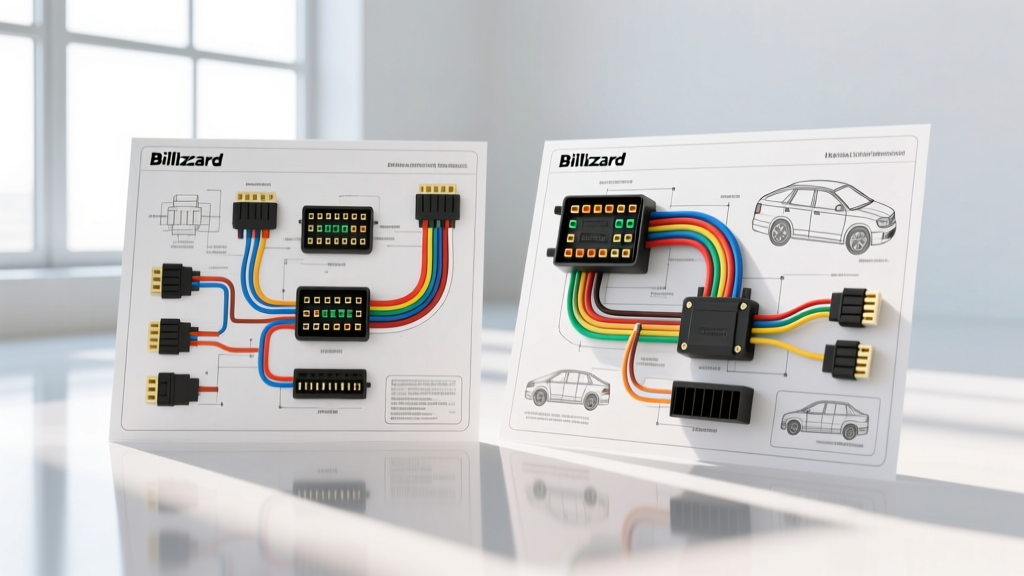
The Evolution of Blizzard Plow Wiring Architecture
Interpreting a Blizzard plow wiring diagram requires an understanding of how snow removal electrical systems have evolved over the last two decades. Blizzard, now a key brand under the Douglas Dynamics umbrella alongside Fisher and Western, has transitioned from isolated, high-current relay systems to sophisticated multiplex and Fleet Flex architectures. For fleet managers and independent owner-operators, selecting the correct vehicle-side harness and plow-side wiring kit is critical for maintaining headlight compliance, solenoid response times, and CAN-bus network integrity on modern heavy-duty trucks.
This guide compares the primary Blizzard wiring systems, breaks down the industry-standard 13-pin connector pinouts, and provides a vehicle-specific selection matrix to ensure your harness matches your truck's Body Control Module (BCM) requirements.
System Comparison: Relay vs. Multiplex vs. Fleet Flex
Before purchasing a replacement harness or upgrading a plow rig, you must identify which electrical architecture your Blizzard plow utilizes. The wiring diagram topology changes drastically between these three systems.
1. Legacy Relay Systems (Pre-2010 Models)
Older Blizzard plows (such as early 810 and 7600 series) relied on traditional heavy-duty solenoids and standard relay logic. The wiring diagrams for these systems feature thick 10 AWG and 8 AWG power wires routed directly through the cab-mounted controller or a heavy-duty toggle switch. While robust, these systems suffer from high voltage drop over long harness runs and require frequent maintenance of the mechanical relay contacts, which are prone to carbon tracking and moisture ingress.
2. Multiplex Wiring Systems
Multiplex systems revolutionized snow plow wiring by sending digital data signals over a single twisted-pair wire rather than running individual 12 AWG control wires for every hydraulic valve. In a Blizzard multiplex diagram, the cab controller communicates with a receiver module mounted on the plow A-frame. This receiver module then triggers localized, solid-state or heavy-duty mechanical solenoids. This reduces the harness weight, minimizes voltage drop, and simplifies the physical routing through the truck's firewall.
3. Fleet Flex Harness Architecture
Fleet Flex is Douglas Dynamics' unified electrical platform. It allows fleet operators to swap Blizzard, Fisher, and Western plows across different truck brands without changing the plow-side harness. The Fleet Flex wiring diagram utilizes standardized vehicle-side modules that translate the truck's specific headlight and BCM signals into a universal output for the plow. If you are upgrading a fleet, transitioning to Fleet Flex harnesses eliminates the need for brand-specific adapter kits and proprietary diagnostic tools.
Blizzard Plow Wiring Diagram: 13-Pin Connector Pinout
Modern Blizzard plows predominantly use the 13-pin round connector for combined lighting and hydraulic control. When troubleshooting or building a custom harness, refer to the following pinout specification table. All wire colors and functions align with standard multiplex and Fleet Flex configurations.
| Pin | Wire Color | Function / Circuit | AWG Size |
|---|---|---|---|
| 1 | Red | 12V Battery Feed (Main Power) | 10 AWG |
| 2 | Black | Chassis Ground (Main) | 10 AWG |
| 3 | White | Lighting Common / Ground | 14 AWG |
| 4 | Green | Left Turn / Stop Signal | 14 AWG |
| 5 | Brown | Running / Parking Lights | 14 AWG |
| 6 | Blue | Right Turn / Stop Signal | 14 AWG |
| 7 | Purple | High Beam Feed | 14 AWG |
| 8 | Yellow | Low Beam Feed | 14 AWG |
| 9 | Orange | Solenoid Control (Raise/Lift) | 12 AWG |
| 10 | Light Blue | Solenoid Control (Angle Left) | 12 AWG |
| 11 | Light Green | Solenoid Control (Angle Right) | 12 AWG |
| 12 | Pink | Controller Data / 12V Ignition | 14 AWG |
| 13 | Gray | Controller Ground | 14 AWG |
When repairing a damaged 13-pin plug, always use SAE J1128 compliant low-tension primary wire with cross-linked polyethylene (XLPE) insulation. Standard PVC insulation will become brittle and crack when exposed to sub-zero temperatures and road salt brine.
Vehicle-Side Harness Selection Guide
Selecting the correct vehicle-side harness is where most installation errors occur. Modern heavy-duty trucks utilize complex CAN-bus networks and Pulse Width Modulation (PWM) headlight circuits. Plugging a standard relay harness into a modern BCM-controlled truck will trigger fault codes and cause the truck's lighting module to shut down.
Ford Super Duty (2017-Present)
Ford's BCM monitors headlight current draw. A Blizzard plow harness for these trucks must include a PWM-to-12V converter module. The wiring diagram routes the truck's low-current headlight signal into the converter, which then triggers a heavy-duty relay to power the plow lights. Failure to use the Ford-specific multiplex adapter will result in the 'Headlamp Fault' dash warning and plow light flickering.
Chevy/GMC HD (2020+ T1 Platform)
The T1 platform uses highly sensitive LED headlight circuits. Blizzard offers a specific T1 harness kit that utilizes high-impedance sense wires to mimic the factory LED load. The diagram requires tapping into the BCM headlight command wires rather than the physical headlight pigtails. Ensure the ground wire for the adapter module is secured to a dedicated chassis ground stud, not a shared sheet-metal bolt.
Ram HD (2019+ with TIPM/Smart Junction Box)
Ram trucks utilize a Totally Integrated Power Module (TIPM) that strictly limits accessory current draw. The Blizzard wiring diagram for modern Rams requires the use of an isolated power distribution block and a TIPM-compatible relay harness. Drawing solenoid control current directly from the cab's accessory circuit will blow internal TIPM traces, requiring a $1,200+ module replacement.
Wire Gauge, Routing, and Grounding Specifications
A wiring diagram is only as effective as the physical installation. Adhering to strict AWG and torque specifications prevents voltage drop, which is the leading cause of slow plow hydraulics and premature motor failure.
- Main Power Feed (Battery to Solenoid): Use 4 AWG or 2 AWG stranded copper wire. For runs exceeding 8 feet, 2 AWG is mandatory to maintain a minimum of 11.5V at the solenoid under heavy hydraulic load.
- Main Ground (Motor to Chassis/Battery): Never rely on the plow hitch pivot points for grounding. Run a dedicated 2 AWG ground wire from the plow motor housing directly to the truck's battery negative terminal or a factory engine block ground stud.
- Firewall Routing: Use a rubber grommet and apply dielectric grease to the harness where it passes through the firewall. Maintain a minimum 4-inch clearance from exhaust manifolds and steering shafts.
Crucial Torque Specifications
| Connection Point | Hardware Size | Torque Spec | Preparation |
|---|---|---|---|
| Battery Terminal Lug | 3/8" Stud | 12 - 15 ft-lbs | Wire brush, apply Noalox anti-oxidant paste |
| Solenoid Post | 5/16" Stud | 8 - 10 ft-lbs | Sand lug surface, star washer against nut |
| Motor Housing Ground | 5/16" Bolt | 10 - 12 ft-lbs | Remove paint to bare metal, coat post-assembly |
Troubleshooting Common Blizzard Harness Failures
When your plow fails to respond, use this diagnostic sequence before replacing expensive hydraulic components:
- Voltage Drop Test: With the plow attempting to raise, measure DC voltage between the battery positive post and the solenoid input terminal. A reading above 0.5V indicates a corroded cable or undersized AWG wire.
- Pin 2 / Pin 3 Ground Continuity: Disconnect the 13-pin plug. Use a multimeter to check continuity between Pin 2 (Main Ground) and Pin 3 (Lighting Ground) at the plow side. If open, the internal A-frame ground splice has corroded and failed.
- Controller Data Faults: If the cab controller displays a 'No Plow Detected' error, check Pin 12 (Pink) and Pin 13 (Gray). The controller requires a clean 12V ignition source and a dedicated ground. Sharing a ground with the plow lighting circuit will introduce AC ripple noise, confusing the multiplex receiver.
Authoritative Resources & References
For OEM diagrams, technical service bulletins (TSBs), and replacement part numbers, always consult the manufacturer and recognized automotive electrical standards:
- Blizzard Snowplows Official Parts & Service Portal - Access model-specific wiring schematics, Fleet Flex adapter guides, and controller firmware updates.
- SAE International J1128 Standard - Specifications for low-tension primary cables used in heavy-duty automotive and snow removal applications.
- Douglas Dynamics Corporate Engineering - Parent company resources for cross-brand multiplex architecture and Fleet Flex integration whitepapers.