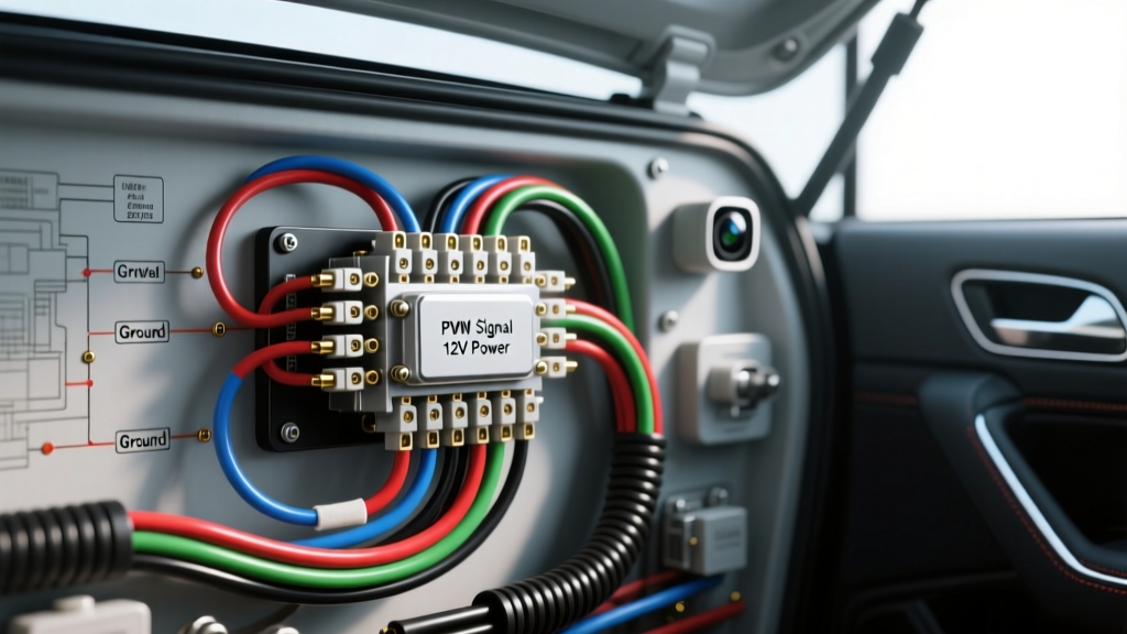
Breaking Down the Cost of Rear View Camera Installation
When planning a vehicle tech upgrade, understanding the true cost of rear view camera installation is critical for budgeting your project. Professional installation rates vary drastically based on vehicle complexity, ranging from a simple $150 labor fee on a 2010 Honda Civic to over $450 for a modern 2022 Ford F-150 requiring CAN-bus integration and tailgate trim removal. For the automotive DIYer, performing this modification yourself not only eliminates the labor premium but also ensures the electrical connections meet rigorous OEM-level standards, avoiding the notorious 'scotch-lock' failures common in budget shop installations.
Professional Shop vs. DIY Modification Cost Matrix
| Project Component | Professional Shop Cost | DIY Upgrade Project Cost | Technical Notes & Specifications |
|---|---|---|---|
| Camera Hardware (IP69K CMOS) | $150 - $350 | $45 - $120 | Require 0.1 Lux low-light rating and 170-degree diagonal FOV. |
| Wiring Harness & Shielded RCA | Included in Labor | $15 - $25 | Must use 75-ohm shielded coaxial RCA to prevent alternator whine. |
| PWM Filter / CAN-Bus Decoder | $60 - $120 | $12 - $35 | Required on 2015+ GM/FCA/Toyota to stabilize 12V camera power. |
| Consumables (Solder, Heat Shrink) | Included | $15 | Use 3M dual-wall adhesive-lined heat shrink for waterproof seals. |
| Labor (2 to 4 Hours) | $200 - $450 | $0 | Shop rates average $110-$150/hr per MECP certification guidelines. |
| Total Estimated Cost | $410 - $945 | $87 - $195 | DIY saves up to 75% while allowing superior wire routing control. |
Core Wiring Requirements: Power, Ground, and Gauge Specs
The most frequent cause of aftermarket camera failure is voltage drop and poor grounding. A rear view camera typically draws between 150mA and 300mA. While this seems negligible, running 18 AWG wire over a 15-foot distance from the engine bay or cabin to the rear license plate housing introduces resistance. For any run exceeding 10 feet, upgrade to 16 AWG stranded copper wire for both the 12V+ power feed and the chassis ground.
Establishing a True Chassis Ground
Do not simply wrap the ground wire around a random trunk hinge bolt. Modern vehicles use extensive e-coating and anti-corrosion treatments that act as electrical insulators. To establish a proper ground:
- Locate an M6 or M8 threaded chassis point in the trunk pan or rear hatch.
- Use a fiberglass scratch pen or 220-grit sandpaper to remove paint and e-coat down to bare, shiny metal in a 1-inch diameter circle.
- Crimp an 18-8 insulated ring terminal using a ratcheting crimp tool (never use pliers).
- Secure the terminal with a zinc-plated steel bolt and a star washer, torquing to 8-10 Nm to prevent vibration loosening without stripping the sheet metal threads.
- Seal the bare metal perimeter with clear silicone or dielectric grease to prevent galvanic corrosion.
Modern Vehicle Integration: Bypassing PWM Reverse Circuits
If you are installing a camera in a vehicle manufactured after 2014, you will likely encounter Pulse Width Modulation (PWM) on the reverse light circuit. Instead of sending a solid 12V DC signal, the Body Control Module (BCM) pulses the voltage rapidly to extend bulb life and monitor for blown fuses. Tapping an aftermarket camera directly into a PWM reverse wire will result in severe flickering, rolling lines, or the camera failing to power on entirely.
The 5-Pin Bosch Relay PWM Bypass Diagram
To extract a clean 12V DC signal from a PWM reverse circuit, you must use a standard 5-pin automotive relay as an isolation buffer. This adheres to SAE J1113 Electromagnetic Compatibility Standards by preventing back-feeding into the vehicle's sensitive CAN-bus network.
| Relay Pin | Wire Color (Standard) | Connection Target | Function |
|---|---|---|---|
| Pin 85 | Black (16 AWG) | Verified Chassis Ground | Energizes the relay coil. |
| Pin 86 | Red (18 AWG) | Reverse Light PWM Trigger (+) | Receives the pulsed signal to close the switch. |
| Pin 30 | Red (16 AWG) | Constant 12V Battery (via 5A Fuse) | Provides the clean, solid 12V source. |
| Pin 87 | Yellow (16 AWG) | Camera 12V+ Power Input | Outputs clean 12V DC to the camera when relay closes. |
| Pin 87a | Not Used | Tape and isolate | Normally closed contact (leave disconnected). |
Expert Note: If the relay clicks rapidly (chattering) due to the PWM frequency, solder a 4700µF 25V electrolytic capacitor and a 1N4001 rectifier diode in parallel across Pins 85 and 86 to smooth the trigger signal.
Video Signal Routing and EMI Mitigation
The analog NTSC/PAL or digital AHD video signal is highly susceptible to Electromagnetic Interference (EMI). The most common symptom of poor routing is 'alternator whine'—a high-pitched buzzing or horizontal scrolling bars on the head unit screen that fluctuate with engine RPM.
According to guidelines referenced by the NHTSA Backup Camera Safety Standards, clear visibility is paramount for safety. To protect the video signal:
- Never run the RCA video cable parallel to the main vehicle wiring harness. If you must cross the main harness, do so at a strict 90-degree angle.
- Avoid the alternator and ignition coils. Route the RCA cable down the opposite side of the vehicle from the alternator (usually the passenger side in LHD vehicles, but verify your specific engine layout).
- Use Ferrite Beads. Snap a ferrite choke onto the RCA cable within 6 inches of the head unit connection to filter out high-frequency RF noise generated by the ECU and infotainment processor.
Head Unit Reverse Trigger Integration
For the infotainment screen to automatically switch to the camera feed when the vehicle is shifted into reverse, the head unit's dedicated reverse trigger wire must be connected to the same 12V source powering the camera.
Common Aftermarket Head Unit Trigger Wire Colors:
• Pioneer: Purple/White stripe
• Kenwood / JVC: Purple
• Alpine: Purple
• Sony: Purple
Connect this trigger wire to the Pin 87 output of your relay (or the clean 12V reverse wire on older, non-PWM vehicles). Do not use a fuse tap at the cabin fuse box for this trigger, as many modern 'reverse' fuses are actually controlled by the BCM and may carry data signals rather than pure 12V power. Always tap at the rear lamp assembly for the most reliable trigger signal.
Summary: Maximizing Your Upgrade Budget
By analyzing the true cost of rear view camera installation, it becomes evident that professional labor accounts for up to 60% of the total project expense. Armed with the correct 16 AWG wiring specifications, a PWM isolation relay, and proper EMI routing techniques, the DIY modifier can execute an upgrade that rivals or exceeds OEM dealership installations for a fraction of the price. Invest your saved labor budget into a premium IP69K-rated camera with a true CMOS sensor and a high-quality shielded RCA harness to ensure longevity and crystal-clear visibility.